Volkswagen Golf / Golf GTI / Golf Variant. Manual - part 845


  Index      Volkswagen     Volkswagen Golf / Golf GTI / Golf Variant - service repair manual 2013 year


Search            copyright infringement  


Content   ..  843  844  845  846   ..


Volkswagen Golf / Golf GTI / Golf Variant. Manual - part 845


-T10096- , Installing
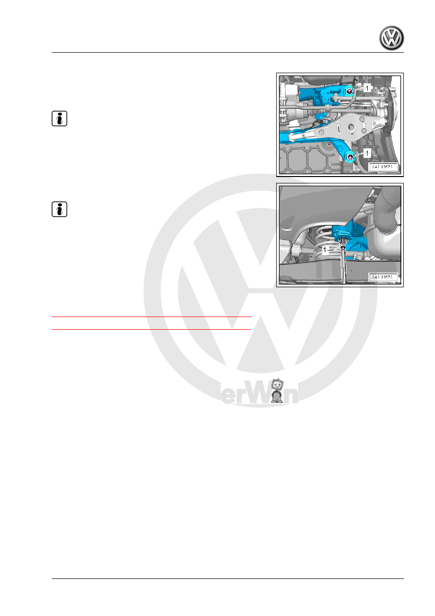
To secure the subframe, the -T10096- must be installed at the

positions -1- one after the other on both sides of the vehicle.
– Remove a hex bolt -1- from both sides.

Note

Only the left side of the vehicle is shown in the illustration.

– Install the - T10096- -1-.

Note

The -T10096- may only be tightened to a maximum of 20 Nm,

otherwise the threads of the locating pins will be damaged.

– Replace the bolts on the subframe one after the other with the

-T10096- -1- on both sides and tighten to 20 Nm.

The subframe position is now secured.

3.3

Subframe, Servicing

⇒ “3.3.1 Front Bonded Rubber Bushing, Replacing”, page 165
⇒ “3.3.2 Rear Bonded Rubber Bushing, Replacing”, page 171

3.3.1

Front Bonded Rubber Bushing, Replac‐

ing

Special tools and workshop equipment required
♦ Tensioning Strap - T10038-
♦ Hydraulic Press - Rear Subframe Bushing Tool Kit - T10263-
♦ Subframe Bushing Assembly Tool Kit - T10356-
♦ Engine and Gearbox Jack - VAS6931-
♦ Hydraulic Press - VAS6178- with Bearing Installer - Wheel

Hub/Bearing Kit - Pressure Head - T10205/13-

♦ Pneumatic/Hydraulic Foot Pump - VAS6179-
♦ Bearing Installer - Wheel Hub/Bearing Kit - T10205A-

Note

If a bonded rubber bushing is faulty, then the bonded rubber

bushing on the opposite side must also be replaced. For the

correct allocation. Refer to the Parts Catalog.

Check the other bearing before switching out a defected bon‐

ded rubber bushing.

If there are any tears or other visible damages, replace the

bonded rubber bushing.

To replace the rubber bonded bushing, the subframe must be

lowered at the front or the rear. It is not necessary to remove

the subframe.

Identify mounting location to subframe before removing the

bonded rubber bushing.

Pressing Out Bonded Rubber Bushing, Front
– Loosen the wheel bolts.
– Raise the vehicle.
– Remove the wheels.
– Remove the spring. Refer to

⇒ “6.4 Spring, Removing and Installing”, page 202

 .

– Remove the rear muffler. Refer to ⇒  Rep. Gr.  26 ; Exhaust

Pipes/Mufflers; Overview - Muffler .

– Remove the clamps -1- on both sides of the vehicle.

Note

Do not disconnect the brake line.

– Secure both sides of the vehicle on the hoist arms using Ten‐

sioning Straps - T10038- .

1 - Tensioning Strap - T10038-

WARNING

The vehicle could slide off the hoist if it is not secured.

– Secure the subframe. Refer to

⇒ “3.2 Subframe, Securing”, page 158

 .

– Mark the installation location of the bonded rubber bushing on

the subframe with a felt-tip pen -1-.

Note

Apply the mark -1- on the subframe in the middle of the recess on

the bonded rubber mounting -2-.

– Use a screwdriver -2- pry off the anti-twist mechanism -1- near

the bonded rubber bushing mounting retaining lugs.

– Lower the subframe approximately 100 mm (3.93 in.) using

the Engine and Gearbox Jack - VAS6931- .

– Unclip the brake line -1- from the clip -arrow- on the left side.

Note

This will destroy the clip, so it will have to be replaced.

– Use the special tools as shown.

1 - Nut - T10263/5-
2 - Press Piece - T10356/1-
3 - Subframe
4 - Subframe Bushing Assembly Tool Kit-Pipe - T10356/2- , side

with shoulder points to subframe
5 - Bearing Installer - Wheel Hub/Bearing Kit - 1 - T10205/1-
6 - Hydraulic Press - VAS6178- with Bearing Installer - Wheel

Hub/Bearing Kit Pressure Head - T10205/13-
7 - Nut - T10263/5-
8 - Threaded Rod - T10263/4-
– Pretension special tools.
– Press out the bonded rubber mount.


Content   ..  843  844  845  846   ..