Volkswagen Golf / Golf GTI / Golf Variant. Manual - part 840
– Disconnect and free up the right and left connector -1- from
the ABS speed sensor.
– Disconnect the right and left electromechanical parking brake
connector -2- from the brake caliper.
– Remove and free up the wiring harness from the retainers
-arrows-.
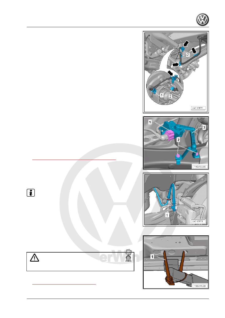
Vehicles with Level Control System Sensor
– Disconnect the connector -1-.
– Remove the bolts -2-.
– Remove the Left Rear Level Control System Sensor - G76-
-3- from the transverse link.
Continuation for all Vehicles
– Remove the springs. Refer to
⇒ “6.4 Spring, Removing and Installing”, page 202
.
– Remove the clamps -1- on both sides of the vehicle.
– Free up the brake lines from the bracket.
Note
Do not disconnect the brake line.
– Remove the left and right brake caliper and with the brake lines
attached secure to the body. Refer to ⇒ Brake System; Rep.
Gr. 46 ; Overview - Rear Brakes .
– Remove the rear muffler. Refer to ⇒ Rep. Gr. 26 ; Exhaust
Pipes/Mufflers; Overview - Muffler .
– Secure both sides of the vehicle on the hoist arms using -
T10038- .
1 - -T10038-
WARNING
The vehicle could slide off the hoist if it is not secured.
– Secure the subframe. Refer to