Volkswagen Golf / Golf GTI / Golf Variant. Manual - part 838


  Index      Volkswagen     Volkswagen Golf / Golf GTI / Golf Variant - service repair manual 2013 year


Search            copyright infringement  


Content   ..  836  837  838  839   ..


Volkswagen Golf / Golf GTI / Golf Variant. Manual - part 838


Mandatory Replacement Parts
♦ Bolts - Subframe to Body
Lower the Subframe with Attachments.
– Loosen the wheel bolts.
– Raise the vehicle.
– Remove the wheels.
– Remove the brake calipers on both sides of the vehicle and

hang on the body.

– Remove the springs. Refer to

⇒ “6.4 Spring, Removing and Installing”, page 202

 .

– Remove the rear muffler. Refer to ⇒  Engine Mechanical, Fuel

Injection and Ignition; Rep. Gr.  26 ; Exhaust Pipes/Mufflers;

Overview - Muffler or ⇒  Engine Mechanical, Fuel Injection and

Glow Plugs; Rep. Gr.  26 ; Exhaust Pipes/Mufflers; Overview

- Muffler

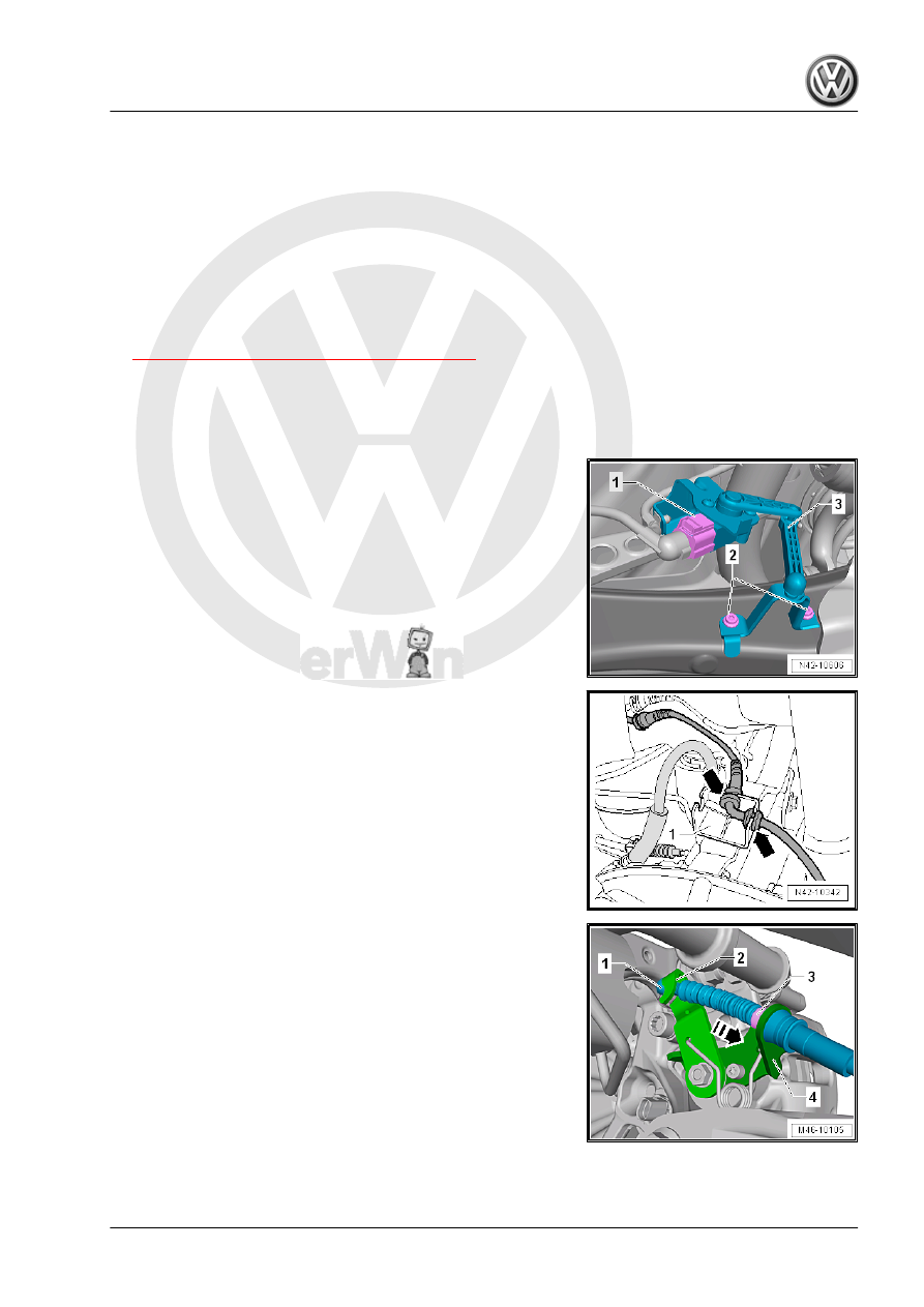
Vehicles with a Vehicle Level Sensor
– Disconnect the connector -1-.
Continuation for All Vehicles
– Disconnect the right and left connectors from the ABS speed

sensor.

– Unclip the right and left speed sensor wires from the bracket

-1- -arrows-.

– Push the lever on the brake caliper -2- in direction of -arrow-.
– Disengage the parking brake cable -1- from the lever on the

brake caliper -2-.

– Squeeze the tabs -3- and remove the parking brake cable

-1- from the bracket -4- on the brake caliper.

– Pull the brake cable -1- out of the retainer -arrow A- on the

bracket -2-.

– Remove the brake cable -1- from the guide -arrow B- on the

bracket -2-.

– Remove the clamps -1- on both sides of the vehicle.
– Free up the brake lines from the bracket.

Note

Do not disconnect the brake line.

– Secure both sides of the vehicle on the hoist arms using Ten‐

sioning Straps - T10038- .

1 - Tensioning Strap - T10038-

WARNING

The vehicle could slide off the hoist if it is not secured.

– Secure the subframe on the two front bolts. Refer to

⇒ “3.2 Subframe, Securing”, page 158

 .

– Remove the bolt from the back of the subframe on the right

side -arrow-.

– Install the Bearing Installer - Component - 3346/2- with the

Subframe Bushing Tool Kit - 3301- and Nut - Component -

3346/3- into the threaded hole in the longitudinal member.

1 - Bearing Installer - Component - 3346/2-
2 - Subframe
3 - Subframe Bushing Tool Kit - 3301-
4 - Nut - Component - 3346/3-
– Remove the left rear bolt from the subframe.
– Turn the Nut - Component - 3346/3- on the Bearing Installer -

Component - 3346/2- until the subframe is lowered by dimen‐

sion -a- = 40 mm.

Subframe with Attachments, Installing
Installation is the reverse of removal, with special attention to the

following:
Tightening Specifications
♦ Refer to 

⇒ “3 Subframe”, page 157

♦ Refer to

⇒ “1.1 Wheel Bolt Tightening Specifications”, page 286

♦ Refer to ⇒  Engine Mechanical, Fuel Injection and Ignition;

Rep. Gr.  26 ; Exhaust Pipes/Mufflers; Overview - Muffler or

⇒  Engine Mechanical, Fuel Injection and Glow Plugs; Rep.

Gr.  26 ; Exhaust Pipes/Mufflers; Overview - Muffler .

• For vehicles with a vehicle level sensor, perform the basic set‐

ting for the wheel damping electronics. Refer to Vehicle Diag‐

nostic Tester .

• On vehicles with level control system sensor, perform head‐

lamp basic setting. Refer to ⇒  Electrical Equipment; Rep. Gr. 

94 ; Headlamp; Headlamp, Adjusting .

– Evaluating need for axle alignment. Refer to

⇒ “3.6 Evaluating Need for Axle Alignment”, page 304

 .

1.2.2

Rear Axle, Lowering, Multi-Link Suspen‐

sion, AWD

Special tools and workshop equipment required
♦ Torque Wrench 1332 40-200Nm - VAG1332-
♦ Engine and Gearbox Jack - VAS6931-

Caution

This procedure contains mandatory replaceable parts. Refer

to component overview prior to starting procedure.

Mandatory Replacement Parts
♦ Bolts - Subframe to Body
Lower the Subframe with Attachments.
– Loosen the wheel bolts.
– Raise the vehicle.
– Remove the wheels.

– Remove the brake calipers on both sides of the vehicle and

hang on the body.

– Remove the springs. Refer to

⇒ “6.4 Spring, Removing and Installing”, page 202

 .

– Remove the rear muffler. Refer to ⇒  Engine Mechanical, Fuel

Injection and Ignition; Rep. Gr.  26 ; Exhaust Pipes/Mufflers;

Overview - Muffler or .⇒  Engine Mechanical, Fuel Injection

and Glow Plugs; Rep. Gr.  26 ; Exhaust Pipes/Mufflers; Over‐

view - Muffler

Vehicles with A Vehicle Level Sensor
– Disconnect the connector -1- from the vehicle level sensor

-2-.

Continuation for All Vehicles
– Disconnect the right and left connectors from the ABS speed

sensor.

– Unclip the right and left speed sensor wires from the bracket

-1- -arrows-.

– Remove the clamps -1- on both sides of the vehicle.
– Free up the brake lines from the bracket.

Note

Do not disconnect the brake line.


Content   ..  836  837  838  839   ..