Volkswagen Golf / Golf GTI / Golf Variant. Manual - part 830
Removing the Inner CV Joint
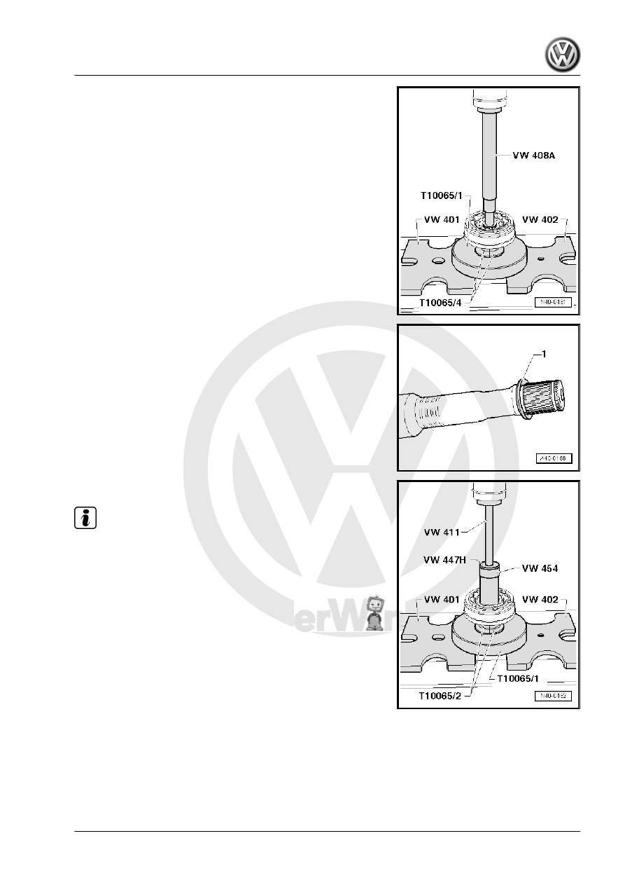
Assembling
Installed Location of the Plate Spring on Inner Joint
1 - Plate Spring
Pressing on Inner CV Joint
Note
Chamfer on inner diameter of ball hub (splines) must face the
contact shoulder on the drive axle.