Volkswagen Golf / Golf GTI / Golf Variant. Manual - part 831
Tightening Clamping Sleeve On Outer Joint
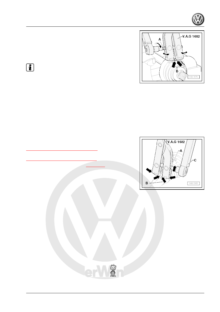
– Position Clamping Pliers - VAG1682A- as shown in illustration.
When doing this, make sure that edges of clamping pliers are
seated in corners -arrows B- of clamp.
– Tension clamp by turning spindle with a torque wrench (do not
tilt clamp tool).
Note
♦
The hard material of the joint boot (compared to rubber) makes
it necessary to use a stainless steel hose clamp. It is only pos‐
sible to tighten the hose clamp with Clamping Pliers -
VAG1682A- .
♦
Tightening specification: 25 Nm.
♦
Use torque wrench -C- with adjustment range 5 to 50 Nm (for
example Torque Wrench 5-50Nm - VAG1331- ).
♦
Be sure thread of spindle -A- of clamp tool moves freely.
Grease with MOS 2 grease if necessary.
♦
If the thread is tight, for example, dirty, the required tensioning
force for the hose clamp will not be achieved in spite of correct
torque specification settings.
Tensioning Clamp On Small Diameter
Outer CV joint, checking. Refer to
⇒ “6.7 Outer CV Joint, Checking”, page 113
Inner CV joint, checking. Refer to
⇒ “6.8 Inner CV Joint, Checking”, page 114
CV joint, checking function. Refer to
6.6.3
Drive Axle, Disassembling and Assem‐
bling, Triple Roller Joint AAR3300i
Special tools and workshop equipment required
♦ Press Plate - VW401-
♦ Press Plate - VW402-
♦ Press Piece - Rod - VW408A-
♦ Press Piece - Multiple Use - VW411-
♦ Press Piece - 37mm - VW416B-
♦ Press Piece - Multiple Use - VW447H-
♦ Hose Clip Pliers - VAG1275A-
♦ Torque Wrench 1331 5-50Nm - VAG1331-
♦ Torque Wrench 1332 40-200Nm - VAG1332-
♦ Clamping Pliers - VAG1682A-
♦ Puller - Driveshaft - T10382/1-
♦ Spindles - T10382/2-