Volkswagen Golf / Golf GTI / Golf Variant. Manual - part 828
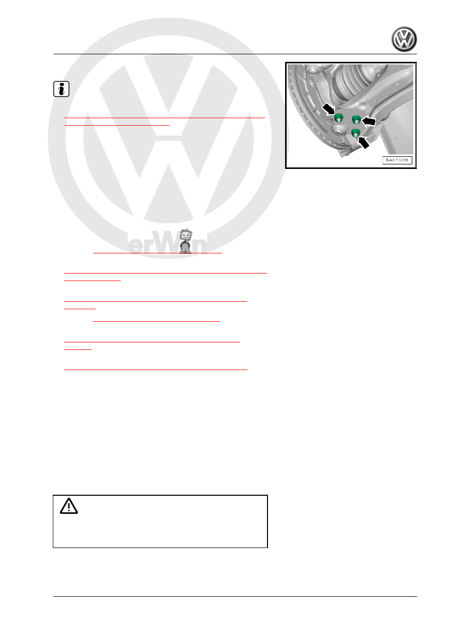
– Attach the ball joint to the control arm -arrows-.
Note
♦
Tighten the nuts -arrows- in curb weight position. Refer to
⇒ “3.8.1 Wheel Bearing in Curb Weight, Lifting Vehicles with
Coil Spring, Front Axle”, page 6
♦
Make sure the ball joint boot is not damaged or twisted.
♦
The level control system sensor lever must point toward vehi‐
cle exterior.
♦
The thread on the vehicle level sensor must be installed into
the exterior hole in the control arm. The tab on the vehicle level
sensor bracket must lock into the inner hole in order to assure
a correct installation position.
– For vehicles with a level control system sensor, perform the
basic setting for the wheel damping electronics using the
⇒ Vehicle diagnostic tester.
Tightening Specifications
♦ Refer to
⇒ “6.2 Overview - Drive Axle”, page 80
♦ Refer to
⇒ “6.4 Drive Axle Threaded Connection, Loosening and Tight‐
♦ Refer to
⇒ “2.1 Overview - Front Level Control System Sensor”,
♦ Refer to
⇒ “2.1 Overview - Subframe”, page 16
♦ Refer to
⇒ “4.1 Overview - Lower Control Arm and Ball Joint”,
♦ Refer to
⇒ “1.1 Wheel Bolt Tightening Specifications”, page 286
♦ Noise insulation bolts. Refer to ⇒ Body Exterior; Rep. Gr. 66 ;
Noise Insulation; Overview - Noise Insulation .
• For vehicles with a level control system sensor, perform a
headlamp basic setting. Refer to ⇒ Electrical Equipment; Rep.
Gr. 94 ; Headlamp; Headlamp, Adjusting .
6.3.4
Drive Axle, Removing and Installing, Tri‐
ple Roller Joint AAR3300i Bolted
Special tools and workshop equipment required
♦ Torque Wrench 1332 40-200Nm - VAG1332-
♦ Drive Shaft Remover - T10520-
Caution
When disassembling and performing repairs on a vehicle, the
drive axles must not hang down loosely and contact the stops
in the joint by over bending.