Volkswagen Golf / Golf GTI / Golf Variant. Manual - part 823


  Index      Volkswagen     Volkswagen Golf / Golf GTI / Golf Variant - service repair manual 2013 year


Search            copyright infringement  


Content   ..  821  822  823  824   ..


Volkswagen Golf / Golf GTI / Golf Variant. Manual - part 823


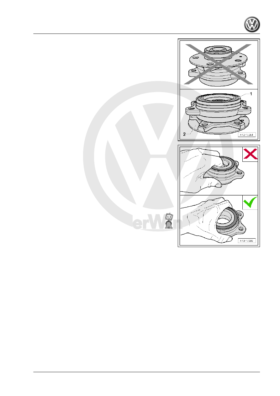
• The wheel bearing -1- must face up in order to remove the

wheel bearing unit.

• Always set the wheel bearing unit down on the wheel hub

-2-.

• Never reach inside when lifting the wheel bearing.
• Hold the wheel bearing only on the outside.
Installing
Install in reverse order of removal. Note the following:

– Tighten nuts -arrows-.

Note

Tighten the nuts -arrows- in curb weight position. Refer to

⇒ “3.8.1 Wheel Bearing in Curb Weight, Lifting Vehicles with

Coil Spring, Front Axle”, page 6

 .

The level control system sensor lever must point toward vehi‐

cle exterior.

The thread on the vehicle level sensor must be installed into

the exterior hole in the control arm. The tab on the vehicle level

sensor bracket must lock into the inner hole in order to assure

a correct installation position.

– For vehicles with a level control system sensor, perform the

basic setting for the wheel damping electronics using the Ve‐

hicle Diagnostic Tester.

Tightening Specifications
♦ Refer to 

⇒ “5.1 Overview - Wheel Bearing”, page 70

♦ Refer to 

⇒ “6.2 Overview - Drive Axle”, page 80

♦ Refer to 

⇒ “2.1 Overview - Subframe”, page 16

♦ Refer to

⇒ “4.1 Overview - Lower Control Arm and Ball Joint”,

page 54

♦ Refer to

⇒ “2.1 Overview - Front Level Control System Sensor”,

page 277

♦ Brake rotor bolt. Refer to ⇒  Brake System; Rep. Gr.  46 ;

Overview - Front Brakes .


VL100

VL107

AAR3300i At‐

tached

AAR3300i Bol‐

ted

Cover between inner joint and

flange shaft

-

X

-

-

Inner joint inserted into transmis‐

sion

(automatic transmission only)

-

-

X

-

6.2

Overview - Drive Axle

⇒ “6.2.1 Overview - Drive Axle, CV Joint VL 100”, page 80
⇒ “6.2.2 Overview - Drive Axle, CV Joint VL 107”, page 82
⇒ “6.2.3 Overview - Drive Axle, Triple Roller Joint AAR3300i”,

page 84

6.2.1

Overview - Drive Axle, CV Joint VL 100

1 - Outer CV Joint

❑ Replace only as com‐

plete unit.

❑ Removing. Refer to

⇒ page 104

 .

❑ Installing: Using a plas‐

tic hammer, drive onto

the shaft as far as the

stop

❑ Checking. Refer to

⇒ “6.7 Outer CV Joint,

Checking”, page 113

 .

2 - Bolt

❑ 200 Nm +180°
❑ Replace after removal
❑ Loosening and tighten‐

ing. Refer to

⇒ “6.4 Drive Axle Threa‐

ded Connection, Loos‐

ening and Tightening”,

page 101

 .

3 - Right Drive Axle
4 - Clamp

❑ Replace after removal
❑ Tensioning. Refer to

⇒ Fig. ““Tensioning

Clamp on Small Diame‐

ter”“ , page 106

5 - CV Boot

❑ Check for tears and

scuffing

❑ Material: polyelastomer

6 - Clamp

❑ Replace after removal
❑ Tensioning. Refer to 

⇒ Fig. ““Tightening Clamping Sleeve on Outer Joint”“ , page 106


Content   ..  821  822  823  824   ..