Volkswagen Golf / Golf GTI / Golf Variant. Manual - part 822


  Index      Volkswagen     Volkswagen Golf / Golf GTI / Golf Variant - service repair manual 2013 year


Search            copyright infringement  


Content   ..  820  821  822  823   ..


Volkswagen Golf / Golf GTI / Golf Variant. Manual - part 822


Using the -T10520- :
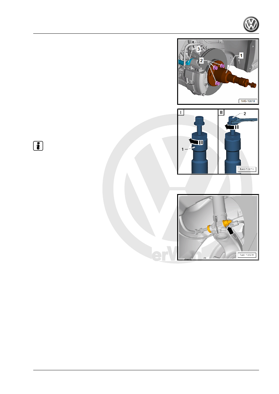
– Secure the -T10520- -1- with three wheel bolts -2- on the wheel

hub, so that the drive axle -3- can be pressed out.

– Follow the specified sequence exactly.
I - Tighten the knurled nut -1- hand-tight.
II - Only turn the bolt -2- using a wrench and press out the drive

axle using the -T10520- .

Note

At the end of the tasks or to set back, the spindles must be brought

back into the original position so that the hydraulic operation can

be used.

– Secure the drive axle to the body using wire.
– Place the -VAS6931- under the wheel bearing housing.

– Remove the threaded connection on the wheel bearing hous‐

ing/suspension strut -arrow-.

Pro

te

c

t

ed

  b

y

  co

p

y

rig

h

t. 

C

o

p

y

in

g

  fo

pr

iv

a

t

e

 o

r

 c

o

m

m

e

r

c

ia

p

u

rp

o

s

e

s

,

 i

n

 p

a

rt

o

r i

n

 w

h

o

le

, 

is

 n

o

t

 p

e

r

m

it

t

e

d

 u

n

l

e

s

s

 a

ut

ho

r

i

s

ed

 b

y

 V

olk

sw

a

ge

n AG

.


V

olk

s

w

a

g

en

 AG do

es 

n

ot g

uar

ante

e

 or a

c

c

ep

t

 a

ny


li

a

b

i

li

t

y

 w

ith

 r

e

s

p

e

c

t

 t

o


th

e

 c

o

rr

e

c

t

n

e

s

s


o

f

in

fo

r

m

a

tio

n

 in

 th

is

 d

o

c

um

en

t.

C

o

py

rig

ht b

y


V

olk

sw

a

ge

n


A

G.

– Insert -3424- into wheel bearing housing slot.

Note

Pay attention that the -3424- is only inserted in the wheel bearing

housing. Only insert it far enough that the suspension strut metal

retainer is not damaged.

– Turn the ratchet 90° and remove it from the -3424- .
– Remove the wheel bearing housing from the suspension strut.

Note

If the wheel bearing housing is being replaced, then the ball joint

must also be replaced. New nuts must be used.

Installing
Install in reverse order of removal while noting the following:

– Tighten nuts -arrows-.

Note

Tighten the nuts -arrows- in curb weight position. Refer to

⇒ “3.8.1 Wheel Bearing in Curb Weight, Lifting Vehicles with

Coil Spring, Front Axle”, page 6

 .The level control system sen‐

sor lever must point toward vehicle exterior.

The thread on the vehicle level sensor must be installed into

the exterior hole in the control arm. The tab on the vehicle level

sensor bracket must lock into the inner hole in order to assure

a correct installation position.

– For vehicles with a level control system sensor, perform the

basic setting for the wheel damping electronics using the Ve‐

hicle Diagnostic Tester.

Tightening Specifications
♦ Refer to 

⇒ “5.1 Overview - Wheel Bearing”, page 70

♦ Refer to

⇒ “4.1 Overview - Lower Control Arm and Ball Joint”,

page 54

♦ Refer to

⇒ “3.1 Overview - Suspension Strut and Upper Control Arm”,

page 44

♦ Refer to 

⇒ “6.2 Overview - Drive Axle”, page 80

♦ Refer to

⇒ “2.1 Overview - Front Level Control System Sensor”,

page 277

♦ Refer to

⇒ “1.1 Wheel Bolt Tightening Specifications”, page 286

♦ Speed sensor bolt. Refer to ⇒  Brake System; Rep. Gr.  45 ;

Sensors; Overview - Front Axle Speed Sensor .

♦ Bolts for cover plate, brake caliper and brake rotor. Refer to ⇒ 

Brake System; Rep. Gr.  46 ; Front Brakes; Overview - Front

Brakes .

5.3

Wheel Bearing Unit, Removing and In‐

stalling

Special tools and workshop equipment required
♦ Torque Wrench 1332 40-200Nm - VAG1332-
Removing
– Remove the drive axle bolt. Refer to

⇒ “6.4 Drive Axle Threaded Connection, Loosening and Tight‐

ening”, page 101

 .

Caution

The wheel bearing must not be under load when the drive axle

threaded connection on the wheel side is loose.
If the wheel bearings are under the load of the vehicle weight,

the wheel bearing will be damaged. This reduces the service

life of the wheel bearings.
The drive axle bolt may be loosened maximum 90° when the

vehicle is standing on its wheels.
Vehicles without a drive axle must not be moved, otherwise the

wheel bearing will be damaged. If a vehicle must be moved,

be sure to note the following:

♦ Install an outer joint in place of the drive axle.
♦ Tighten the outer joint to 120 Nm.

– Loosen the wheel bolts.
– Raise the vehicle.
– Remove the wheel.
– Remove the brake caliper and tie it to the vehicle body with

wire. Refer to ⇒  Brake System; Rep. Gr.  46 ; Front Brakes;

Overview - Front Brakes .

– Remove the brake rotor. Refer to ⇒  Brake System; Rep. Gr. 

46 ; Overview - Front Brakes .

Vehicles with Level Control System Sensor
– Remove the nut -1-.
– Remove the bracket -2- for the Left Front Level Control System

Sensor - G78- or  Right Front Level Control Sensor - G289-

from the control arm -3-.

Continuation for all Vehicles

– Remove the hex nut -1- from the coupling rod -3-.
– Remove the coupling rod -3- from the stabilizer bar -2-.

– Remove the nuts -arrows-.
– Remove the control arm from the ball joint.
– Remove the drive axle outer joint from the wheel hub.
– Secure the drive axle to the body using wire.
– Attach the ball joint to the control arm again -arrows-.

– Remove the bolts -arrows-.
– Remove wheel bearing unit from wheel bearing housing.

Caution

• Avoid contaminating with dirt and damaging the seal when

lifting, setting down/storing.


Content   ..  820  821  822  823   ..