Volkswagen Golf / Golf GTI / Golf Variant. Manual - part 755


  Index      Volkswagen     Volkswagen Golf / Golf GTI / Golf Variant - service repair manual 2013 year


Search            copyright infringement  


Content   ..  753  754  755  756   ..


Volkswagen Golf / Golf GTI / Golf Variant. Manual - part 755


Test Sequence:

Note

The output diagnostic test mode checks the fuel pump function.

– Pay attention to all safety precautions. Refer to

⇒ “1 Safety Precautions”, page 1

 .

– Follow the guidelines for clean working conditions. Refer to

⇒ “3.1 Parking/Auxiliary Heater and Fuel System Clean Work‐

ing Conditions”, page 4

 .

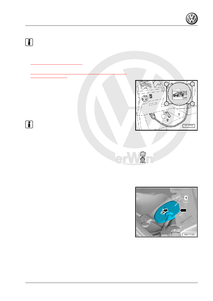
– Connect the Vehicle Diagnostic Tester -1- as follows:
– Connect the diagnostic cable connector -2- to the diagnostic

connection inside the driver footwell.

– Switch the ignition on.
– Select the fuel pump output diagnostic test mode in OBD.
The fuel pump must now accelerate slowly up to the maximum

RPM.

Note

The fuel pump runs very quietly.

If the output diagnostic test mode is performed several times

in succession, it may be necessary to briefly start the motor

before repeating the output diagnostic test mode.

– Switch off the ignition.
If the fuel pump does not start:
Golf Sportsvan:
– Remove the right rear seat. Refer to ⇒  Body Interior; Rep. Gr. 

72 ; Rear Seats; Bench Seat / Single Seat, Removing and In‐

stalling .

– Partially loosen the cover -1- in the carpet at the separating

line -arrow-.

– Do not separate the cover completely from the carpet so that

later it will be installed correctly.

– Only loosen so far that the cover can be folded up.
– Fold up the cover in the direction of the -arrow-.
Golf and Golf Wagon:
– Remove the rear bench seat. Refer to ⇒  Body Interior; Rep.

Gr.  72 ; Rear Seats; Bench Seat / Single Seats, Removing

and Installing .

Continuation for All Vehicles:
– Unclip the right sealing flange cover -1- at the tabs -arrows-

using the -3409- .

– Unclip the grommet -1- downward out of the cover -2-.
– Guide the cover -2- on the wiring harness -3- toward the rear.

– Pull on the connector -arrow- without pressing the release to

make sure the connection is secure.

– Repeat the fuel pump output diagnostic test mode if the con‐

nector was not connected correctly.

– Release and disconnect the connector -arrow-.
– Check the contacts on the connector and on the fuel delivery

unit for damage.

– Connect the -VAS5565- to the connector and to the fuel de‐

livery unit.

– Connect an Analog/Digital Multimeter to the wires -1- and -5-

on the -VAS5565- .

– Switch the ignition on.
• Specified value: approximately battery voltage
If the specified value is not obtained:
– Locate and repair the open circuit according to the wiring dia‐

gram. Refer to ⇒ Wiring diagrams, Troubleshooting & Com‐

ponent locations.

If no faults can be found:

WARNING

The fuel line is under pressure.
Fuel poses a risk of injury to the eyes and skin.
Wear protective eyewear and protective clothing to avoid injury

and contact with skin. Place a cleaning cloth around the con‐

nection  point  before  loosening  hose  connections.  Carefully

open the connection point to release the pressure.

– Drain the fuel tank. Refer to

⇒ “1.3 Fuel Tank, Draining”, page 35

 .

– Remove the fuel lines -1- from the flange. Disconnect the con‐

nector couplings. Refer to

⇒ “4.1 Connector Couplings, Disconnecting”, page 62

 .

Vehicles with Parking Heater:
– Remove the fuel line -2- to the Metering Pump - V54- for the

parking heater on the sealing flange.

– Open the lower clamp to do this.
– Carefully remove the fuel line -2-.

Continuation for All Vehicles:
– Open the locking ring using the -T10202- .
– Check if the wiring between the flange and fuel pump is con‐

nected.

– Inspect the contacts for damage.
If no open circuits are found:
– If the fuel pump is faulty, replace the fuel delivery unit. Refer

to

⇒ “2.2 Fuel Delivery Unit/Fuel Level Sensor, Removing and

Installing”, page 52

 .

8.1.3

Fuel Pressure, Checking

Special tools and workshop equipment required
♦ Trim Removal Wedge - 3409-
♦ Pressure Tester Kit - VAS6550-
♦ Pressure Tester Kit - Adapter Set - Hose 3 - VAS6550/3-3-
♦ Pressure Tester Kit - Adapter Set - Hose 4 - VAS6550/3-4-
♦ Vehicle Diagnostic Tester
Conditions:
• Power supply is OK.

⇒ “8.1.1 Fuel Pumps, Checking Function and Power Supply”,

page 81

 .

– Pay attention to all safety precautions. Refer to

⇒ “1 Safety Precautions”, page 1

 .

– Follow the guidelines for clean working conditions. Refer to

⇒ “3.1 Parking/Auxiliary Heater and Fuel System Clean Work‐

ing Conditions”, page 4

 .

– Remove the supply line -1-. Disconnect the connector cou‐

plings. Refer to

⇒ “4.1 Connector Couplings, Disconnecting”, page 62

 .

WARNING

The fuel line is under pressure.
Fuel poses a risk of injury to the eyes and skin.
Wear protective eyewear and protective clothing to avoid injury

and contact with skin. Place a cleaning cloth around the con‐

nection  point  before  loosening  hose  connections.  Carefully

open the connection point to release the pressure.

– Collect leaking fuel with a cleaning cloth.

– Connect the -VAS6550/1- to the connection -A- on the -

VAS6550- .

– Connect the -VAS6550/1- to the fuel supply line -1- to the en‐

gine.

– Connect the -VAS6550/2- to the connection -B- on the -

VAS6550- .

– Connect the fuel line to the fuel tank with the -VAS6550- via

the -VAS6550/2- .

– Pull on the connector couplings to check them for secure fit.


Content   ..  753  754  755  756   ..