Volkswagen Golf / Golf GTI / Golf Variant. Manual - part 756
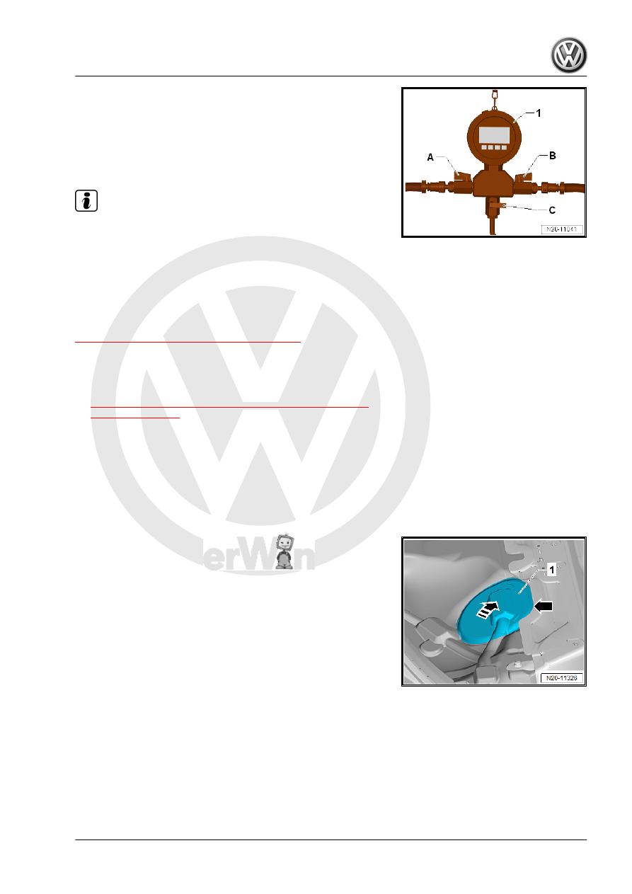
– Make sure that the drain valve -C- on the Pressure Tester
-1- is closed.
– The shut-off valves -A- and -B- on the Pressure Tester Kit -
VAS6550- -1- are opened.
– Connect the Vehicle Diagnostic Tester .
– Select the fuel pump output diagnostic test mode in OBD.
Note
♦
The fuel pump is now activated to build up the fuel pressure.
♦
If the output diagnostic test mode is performed several times
in succession, it may be necessary to briefly start the motor
before repeating the output diagnostic test mode.
– Read the fuel pressure on the pressure gauge.
• Specified value: 4.0 to 7.0 bar.
If the fuel pressure is OK, check the residual pressure. Refer to
⇒ “8.1.5 Residual Pressure, Checking”, page 95
If the specified value is exceeded:
– The pressure relief valve in the fuel delivery unit is faulty.
– Replace the fuel delivery unit. Refer to
⇒ “2.2 Fuel Delivery Unit/Fuel Level Sensor, Removing and
.
If the specified value is not obtained:
Proceed as follows to check the fuel pressure at the fuel delivery
unit:
Golf Sportsvan:
– Remove the right rear seat. Refer to ⇒ Body Interior; Rep. Gr.
72 ; Rear Seats; Bench Seat / Single Seat, Removing and In‐
stalling .
– Partially loosen the cover -1- in the carpet at the separating
line -arrow-.
– Do not separate the cover completely from the carpet so that
later it will be installed correctly.
– Only loosen so far that the cover can be folded up.
– Fold up the cover in the direction of the -arrow-.
Golf and Golf Wagon:
– Remove the rear bench seat. Refer to ⇒ Body Interior; Rep.
Gr. 72 ; Rear Seats; Bench Seat / Single Seats, Removing
and Installing .