Volkswagen Golf / Golf GTI / Golf Variant. Manual - part 720


  Index      Volkswagen     Volkswagen Golf / Golf GTI / Golf Variant - service repair manual 2013 year


Search            copyright infringement  


Content   ..  718  719  720  721   ..


Volkswagen Golf / Golf GTI / Golf Variant. Manual - part 720


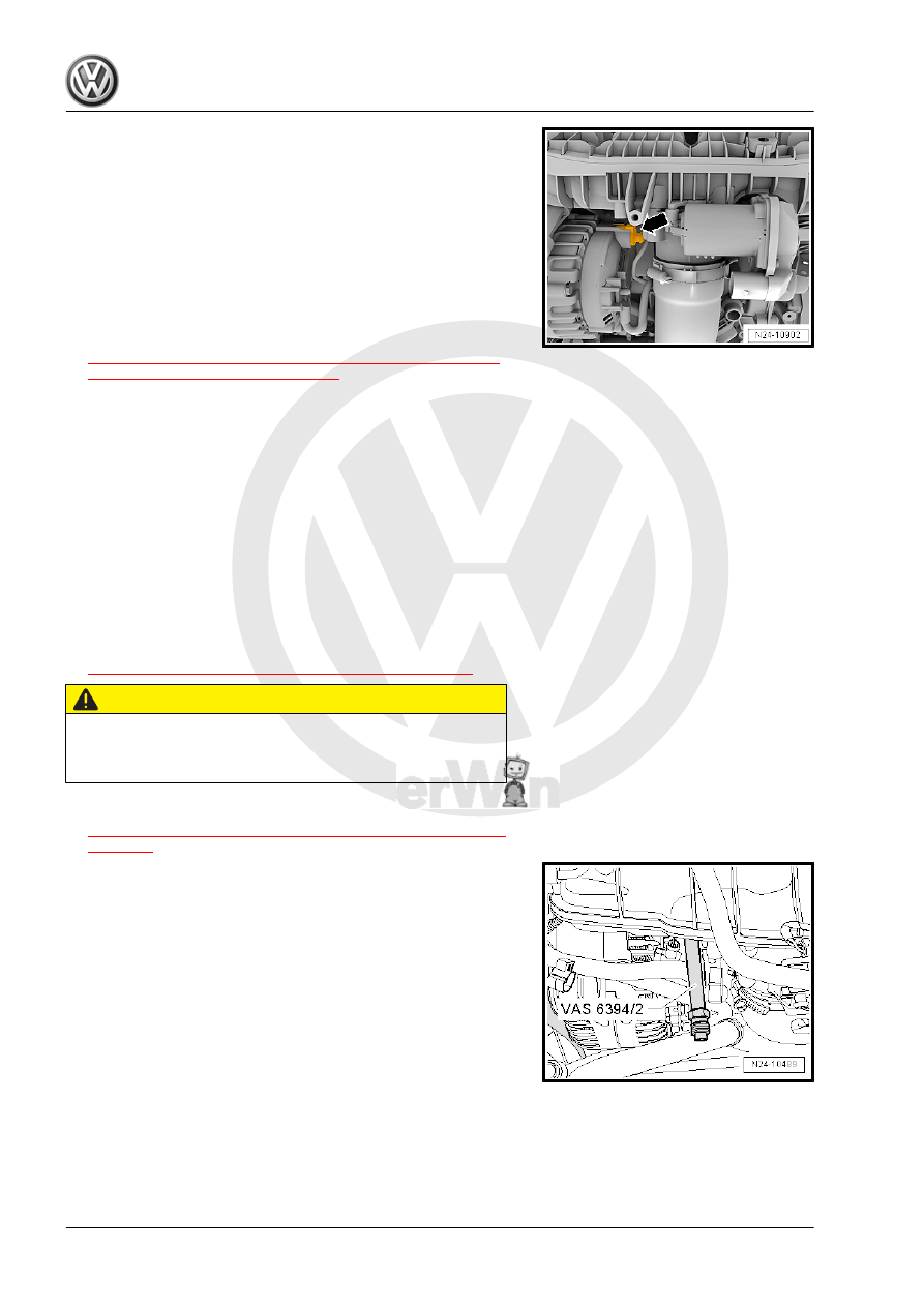
– Remove the connector -arrow- from the generator, otherwise

the socket can get hooked to the connector.

– Loosen and remove the Fuel Pressure Sensor - G247- -1- us‐

ing the Socket - 27mm - T40218-

Installing
– Coat the Fuel Pressure Sensor - G247- sealing point with

clean engine oil.

– Install in reverse order of removal.
Tightening Specifications
♦ Refer to

⇒ “4.2.1 Overview - Intake Manifold Lower Section with Fuel

Rail, Direct Fuel Injection”, page 300

 .

5.3

Fuel Pressure Sensor - G247- , Check‐

ing

Special tools and workshop equipment required
♦ Pressure Sensor Tester - VAS6394/1-
♦ Adapter - VAS6394/2-
♦ Vehicle Diagnostic Tester - Test Adapter - 3 Pin - VAS5570-
♦ Torque Wrench 1331 5-50Nm - VAG1331-
♦ Vehicle Diagnostic Tester
Work Procedure
– Remove the engine cover. Refer to

⇒ “3.1 Engine Cover, Removing and Installing”, page 38

 .

CAUTION

Fuel system is under high pressure.
Risk of injury from fuel spraying out.
– Reducing the fuel high pressure.

– Remove the Fuel Pressure Sensor - G247- . Refer to

⇒ “5.2  Fuel Pressure Sensor G247 , Removing and Installing”,

page 314

 .

– Install the Pressure Sensor Tester - Adapter - VAS6394/2- in‐

stead of the Fuel Pressure Sensor - G247- . Tighten it to the

tightening specification for the Fuel Pressure Sensor - G247- .

– Open the Digital Manometer - VAS6394/1- sealing plug -2-

and install the removed Fuel Pressure Sensor - G247- in the

opening using the tightening specification.

– Use the Vehicle Diagnostic Tester - Test Adapter - 3 Pin -

VAS5570- in order establish the electrical connection between

the vehicle and the Fuel Pressure Sensor - G247- .

Note

For further work the engine must be started. For this reason the

intake hose and air filter housing must be reinstalled.

– Connect the Vehicle Diagnostic Tester .
– Turn on the ignition.
– Select “engine electronics” in On Board Diagnostics (OBD).
– Select “measured values”
– Select “fuel pressure” from the list.
The current value is displayed in field, which the Fuel Pressure

Sensor - G247- reports to the Engine Control Module (ECM).

– Briefly press the button -A- once to turn on the Digital Man‐

ometer - VAS6394/1- .

Note

Holding the button -A- for two seconds switches on the illumina‐

tion for 20 seconds.

The Digital Manometer - VAS6394/1- must display 0 bar/psi; if this

is not the case, press the button -C- once briefly to set it back to

zero.

– Connect the Digital Manometer - VAS6394/1- to the Pressure

Sensor Tester Adapter - VAS6394/2- .

– Start the engine.
– Compare the pressure shown in the Digital Manometer -

VAS6394/1- with the actual value in the Vehicle Diagnostic

Tester

• The pressures may have a maximum difference of 5 bar (72.5

psi).

– If the difference is greater than 5 bar (72.5 psi), test a new Fuel

Pressure Sensor - G247- .

CAUTION

Fuel system is under high pressure.
Risk of injury from fuel spraying out.
– Reducing the fuel high pressure.

– Insert the new Fuel Pressure Sensor - G247- in the Digital

Manometer - VAS6394/1- .

– Repeat the test with the new Fuel Pressure Sensor - G247-

and compare both values.

If the Measured Values Do Not Now Match Again
– Check the electrical connectors between the Fuel Pressure

Sensor - G247- and the ECM. Refer to ⇒ Wiring diagrams,

Troubleshooting & Component locations.

If the Measured Values Now Match
– Install a new Fuel Pressure Sensor - G247- . Refer to

⇒ “5.2  Fuel Pressure Sensor G247 , Removing and Installing”,

page 314

 .

Tightening Specifications
♦ Refer to

⇒ “4.2.1 Overview - Intake Manifold Lower Section with Fuel

Rail, Direct Fuel Injection”, page 300

 .

5.4

Low Fuel Pressure Sensor - G410- , Re‐

moving and Installing

Caution

This procedure contains mandatory replaceable parts. Refer

to component overview prior to starting procedure.

Mandatory Replacement Parts
♦ O-ring - Low fuel Pressure Sensor

Note

Only on vehicles with intake-manifold fuel injection

Removing
– Remove the engine cover. Refer to

⇒ “3.1 Engine Cover, Removing and Installing”, page 38

 .

– Disconnect the connector -6- from the Low Fuel Pressure

Sensor - G410- .

– Remove the clamps -2-.
– Remove the Low Fuel Pressure Sensor - G410- -1- from the

fuel rail.

– Remove the Low Fuel Pressure Sensor - G410- -1- from the

adapter -2-.

Installing
– Replace the O-ring -arrow-.
– Bolt together the adapter -2- and the Low Fuel Pressure Sen‐

sor - G410- -1-.


Content   ..  718  719  720  721   ..