Volkswagen Golf / Golf GTI / Golf Variant. Manual - part 718
 

  Index      Volkswagen     Volkswagen Golf / Golf GTI / Golf Variant - service repair manual 2013 year


Search            copyright infringement  


Content   ..  716  717  718  719   ..


Volkswagen Golf / Golf GTI / Golf Variant. Manual - part 718


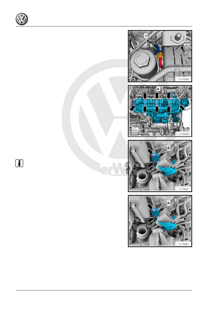
– Disconnect the connector -1- from the Intake Manifold Runner

Position Sensor - G336- .

– Remove the nuts -A- from the intake manifold and remove the

bolts -arrows- using the Torx Socket - T30 - T10347- .

– Pull the intake manifold slightly away from the cylinder head

and remove the bolts -arrows- for the bracket -A-.

– Remove the intake manifold from the cylinder head.

Note

Cover the intake channels with a clean cloth.

Installing
– If the connections on the high pressure pump were loosened,

replace the connections.

– Position the intake manifold on the cylinder head and tighten

the connector bracket -A-.

– Tighten the nuts -A- hand-tight.
– Tighten the bolts -arrows- evenly, working from the inside to

the outside. Use the Torx Socket - T30 - T10347- .

– Install in reverse order of removal.
Tightening Specifications
♦ Refer to 

⇒ “4.1 Overview - Intake Manifold”, page 296

 .

♦ Refer to

⇒ “4.2.2 Overview - Intake Manifold Lower Section with Fuel

Rail, Multiport Fuel Injection”, page 302

 .

4.4

Fuel Rail, Removing and Installing, Di‐

rect Fuel Injection

Note

Intake manifold must be removed, Intake manifold, removing.

Refer to

⇒ “4.3 Intake Manifold, Removing and Installing”, page 304

 .

– Remove all electrical connectors from the fuel injectors.
– Remove bolts -arrows- from the fuel rail.
– Remove fuel rail from the cylinder head.
Installing
– Install in reverse order of removal.
– Install the intake manifold. Refer to

⇒ “4.3 Intake Manifold, Removing and Installing”, page 304

 .

Tightening Specifications
♦ Refer to

⇒ “4.2.1 Overview - Intake Manifold Lower Section with Fuel

Rail, Direct Fuel Injection”, page 300

 .

♦ Refer to

⇒ “4.2.1 Overview - Intake Manifold Lower Section with Fuel

Rail, Direct Fuel Injection”, page 300

4.5

Throttle Valve Control Module - GX3- ,

Removing and Installing

Caution

This procedure contains mandatory replaceable parts. Refer

to component overview prior to starting procedure.

Mandatory Replacement Parts
♦ Seal - Throttle Valve Control Module
The Throttle Valve Control Module - GX3- is comprised of:
♦ EPC Throttle Drive - G186-
♦ EPC Throttle Drive Angle Sensor 1 - G187-
♦ EPC Throttle Drive Angle Sensor 2 - G188-

Removing
– Open the retainer in direction of -arrow- and remove the cover

-2-.

– Remove the engine cover. Refer to

⇒ “3.1 Engine Cover, Removing and Installing”, page 38

 .

– Remove the bolts -1 and 3-.

– Free up the coolant hose -2-.
– Open the retaining tabs in direction of -arrows-, remove the

upper air duct -1-.

– Remove the left and right bolts -arrow-.
– Unclip and remove the lower section -1- of the air duct.
– Remove the noise insulation. Refer to ⇒  Body Exterior; Rep.

Gr.  66 ; Noise Insulation; Overview - Noise Insulation .

Note

Ignore item -1-.

– Loosen the hose clamp -2-, remove the air duct hose from the

charge air cooler.

– Free up the coolant hose -3-.
– Remove the connector -1- from the Charge Air Pressure Sen‐

sor - G31- .

– Remove the bolts -arrows-.
– Loosen air guide hose clamp -2- and remove the air duct hose

from the Throttle Valve Control Module - GX3- .

– Remove the air duct hose downward.
– Disconnect the connector -1- from the Throttle Valve Control

Module - GX3- .

– Remove the Throttle Valve Control Module - GX3- bolts

-arrows- from below and remove Throttle Valve Control Mod‐

ule - GX3- .

Installing
– Install in reverse order of removal.
– Clean the sealing ring surface.
– Replace the seal.
Tightening Specifications
♦ Refer to 

⇒ “4.1 Overview - Intake Manifold”, page 296

 .

– After replacing the Throttle Valve Control Module , it must be

adapted to the Engine Control Module - J623- . Use a Vehicle

Diagnostic Tester to do so.

4.6

Throttle Valve Control Module, Cleaning

Special tools and workshop equipment required
♦ Acetone, commercially available
♦ Brush

Note

♦

If a new Engine Control Module - J623- is installed, then it must

be adapted to the throttle valve control module.

♦

Dirt and coking on the end stop can produce incorrect adap‐

tation values.

♦

The throttle valve connections must not be damaged when

cleaning.


Content   ..  716  717  718  719   ..