Volkswagen Golf / Golf GTI / Golf Variant. Manual - part 717
4.3
Intake Manifold, Removing and Instal‐
ling
Special tools and workshop equipment required
♦ Torx Socket - T30 - T10347-
♦ Flare Nut Attachment - 17mm - T10456-
If the intake manifold is removed or replaced, the Intake Manifold
Runner Position Sensor - G336- must be adapted to the Engine
Control Module - J623- .
Removing
– Disconnect the battery. Refer to ⇒ Electrical Equipment; Rep.
Gr. 27 ; Battery; Battery, Disconnecting and Connecting .
– Remove the engine cover. Refer to
⇒ “3.1 Engine Cover, Removing and Installing”, page 38
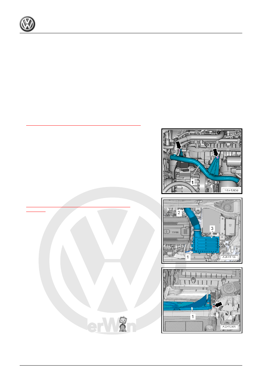
– Remove the bolts -arrows-.
– Remove the air filter housing -3-. Refer to
⇒ “3.2 Air Filter Housing, Removing and Installing”,
– Remove the left and right bolt -arrow-.
– Unclip and remove the lower section -1- of the air duct.
– Remove the noise insulation. Refer to ⇒ Body Exterior; Rep.
Gr. 66 ; Noise Insulation; Overview - Noise Insulation .