Volkswagen Golf / Golf GTI / Golf Variant. Manual - part 715
4
Intake Manifold
⇒ “4.1 Overview - Intake Manifold”, page 296
.
⇒ “4.2 Overview - Intake Manifold Lower Section with Fuel Rail”,
page 300
⇒ “4.3 Intake Manifold, Removing and Installing”, page 304
⇒ “4.4 Fuel Rail, Removing and Installing, Direct Fuel Injection”,
.
⇒ “4.5 Throttle Valve Control Module GX3 , Removing and In‐
.
⇒ “4.6 Throttle Valve Control Module, Cleaning”, page 311
4.1
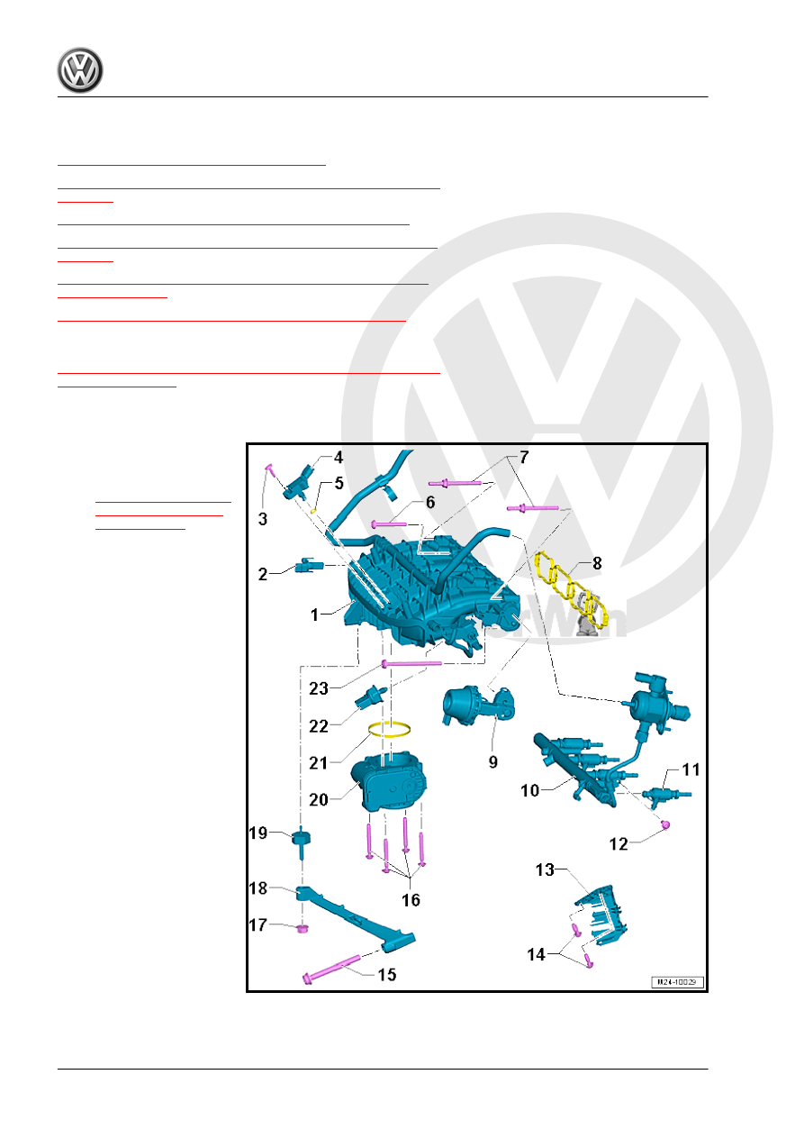
Overview - Intake Manifold
⇒ “4.1.1 Overview - Intake Manifold, without Intake-Manifold Fuel
4.1.1
Overview - Intake Manifold, without Intake-Manifold Fuel Injection
1 - Intake Manifold
❑ Removing and instal‐
ling. Refer to
2 - Intake Manifold Runner Po‐
sition Sensor - G336-
❑ The Intake Manifold
Runner Position Sensor
- G336- needs to be
adapted to the Engine
Control Module - J623-
each time the sensor is
removed and installed
or replaced. See “Gui‐
ded Functions”; to do
so, use a Vehicle Diag‐
nostic Tester .
3 - Bolt
❑ 5 Nm
❑ Intake Air Temperature