Volkswagen Golf / Golf GTI / Golf Variant. Manual - part 714


  Index      Volkswagen     Volkswagen Golf / Golf GTI / Golf Variant - service repair manual 2013 year


Search            copyright infringement  


Content   ..  712  713  714  715   ..


Volkswagen Golf / Golf GTI / Golf Variant. Manual - part 714


Note

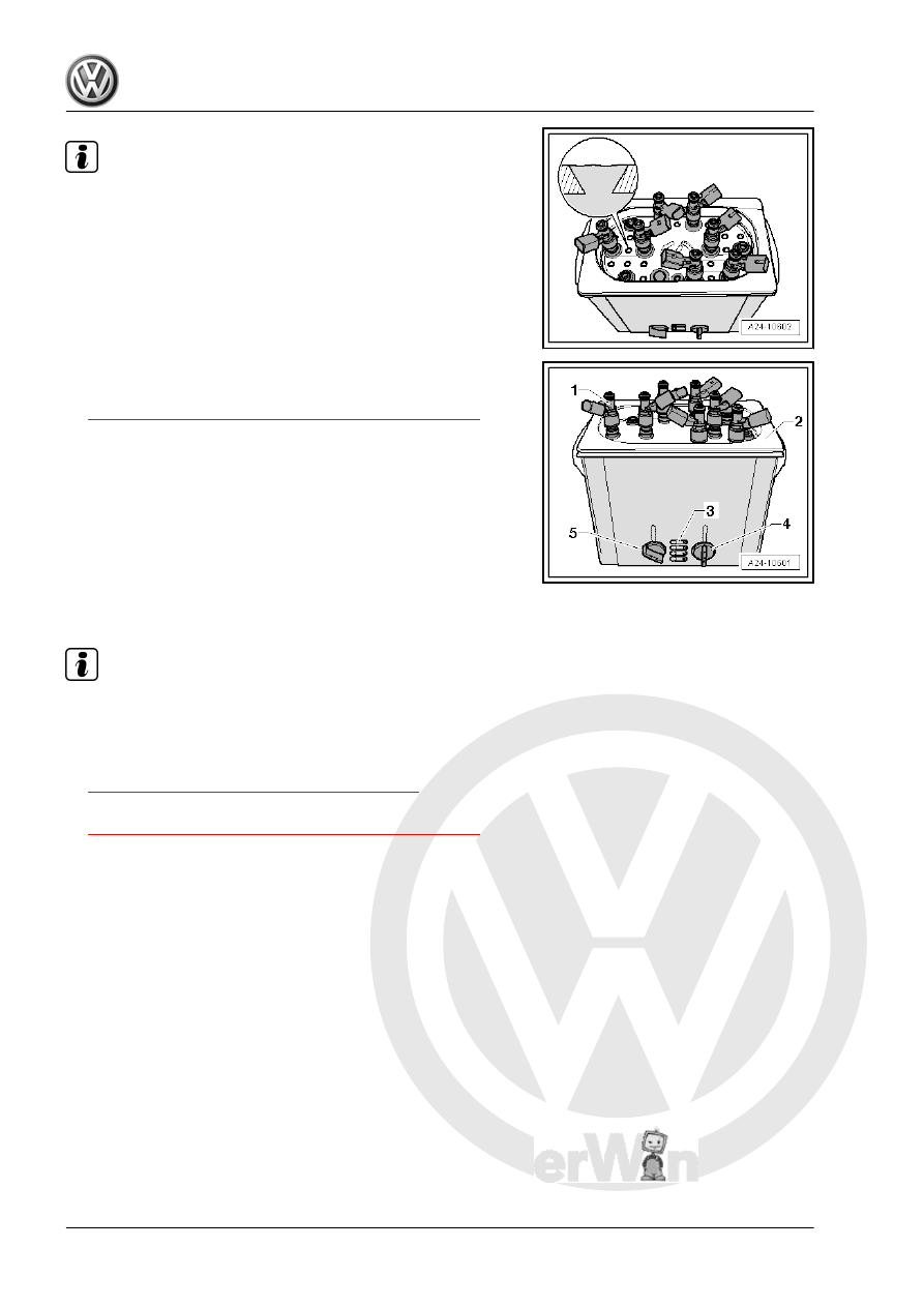
Fill the ultrasonic device up to the upper edge of the holes with

cleaner (see the magnified area of the illustration).

Observe the safety precautions and the operating instructions

for the ultrasonic device.

Cleaning
– Remove the fuel injectors. Refer to

⇒ “2.2 Fuel Injectors, Removing and Installing”, page 285

 .

– The ultrasonic device must be filled with cleaning fluid.
– Install the combustion chamber fuel injectors -1- all the way

into the Mounting Plate for Injection Modules - VAS6418/1-

-2-.

– Dip the combustion chamber fuel injectors into the cleaner with

the Mounting Plate for Injection Modules - VAS6418/1- .

– Set the temperature control -4- to 50 °C (122 °F).
– Set the time control -5- to 30 minutes.
– Turn on the ultrasonic device -3-.

Note

The time begins counting down once the cleaning temperature

reaches 50 degrees.

– Always replace the combustion chamber seal (Teflon seal) af‐

ter cleaning each combustion chamber fuel injector. Refer to

⇒ “2.4 Fuel Injector Seals, Replacing”, page 288

 .

– Install the combustion chamber fuel injectors. Refer to

⇒ “2.2 Fuel Injectors, Removing and Installing”, page 285

 .

3

Air Filter

⇒ “3.1 Overview - Air Filter Housing”, page 293

 .

⇒ “3.2 Air Filter Housing, Removing and Installing”, page 294

 .

3.1

Overview - Air Filter Housing

1 - Air Guide- Lower Section

❑ On the lock carrier

2 - Air Guide- Upper Section

❑ On the lock carrier

3 - Cover

❑ For the air guide

4 - Bolt

❑ 2 Nm

5 - Seal
6 - Air Guide Hose
7 - Screw-Type Clamp
8 - Air Guide Hose
9 - Spring Clamp
10 - Bolts

❑ 1.5 Nm

11 - Air Filter Housing Upper

Section

❑ Clean off dirt, leaves

and salt residue

12 - Air Filter

❑ Use the original-air filter

element. Refer to the

Parts Catalog.

❑ For the change inter‐

vals. Refer to the

⇒ Maintenance ; Book‐

let  36.1 ; Service Work;

Service Tables .

❑ Removing and instal‐

ling. Refer to ⇒ Mainte‐

nance ; Booklet  36.1 ; Procedure Descriptions; Air Filter, Cleaning Housing and Replacing Filter .

13 - Insert

❑ For the air filter lower section

14 - Air Filter Housing Lower Section

❑ Clean off dirt, leaves and salt residue

15 - Rubber Buffer
16 - O-Ring

❑ Replace if damaged

17 - Water Drain Hose

❑ With valve
❑ Clean

18 - Air Guide

❑ On the air filter housing lower section

3.2

Air Filter Housing, Removing and Instal‐

ling

Removing
– Remove the bolts -1 and 3-.
– Open the lock in direction of -arrow- and remove the cover

-2-.

– Free up the coolant hose -2-.
– Release the locking mechanism in direction of -arrows- and

remove the air guide upper section -1-.

– Disconnect the vacuum hose -1-.
– Loosen the clamp -2- and remove the air guide hose.
– Carefully remove the air filter housing -3-.
Installing

Note

Use silicone-free lubricant to mount the air guide hose.

Secure hose connections with standard production clamps.

Refer to the Parts Catalog.

– Check the air guide hose (clean air side) for salt residue, dirt

and leaves.

– Check intake channels up to the air filter insert for dirt.
– Install the air filter housing.

Note

The water drain hose must be routed straight down and without

any bends.


Content   ..  712  713  714  715   ..