Volkswagen Golf / Golf GTI / Golf Variant. Manual - part 691


  Index      Volkswagen     Volkswagen Golf / Golf GTI / Golf Variant - service repair manual 2013 year


Search            copyright infringement  


Content   ..  689  690  691  692   ..


Volkswagen Golf / Golf GTI / Golf Variant. Manual - part 691


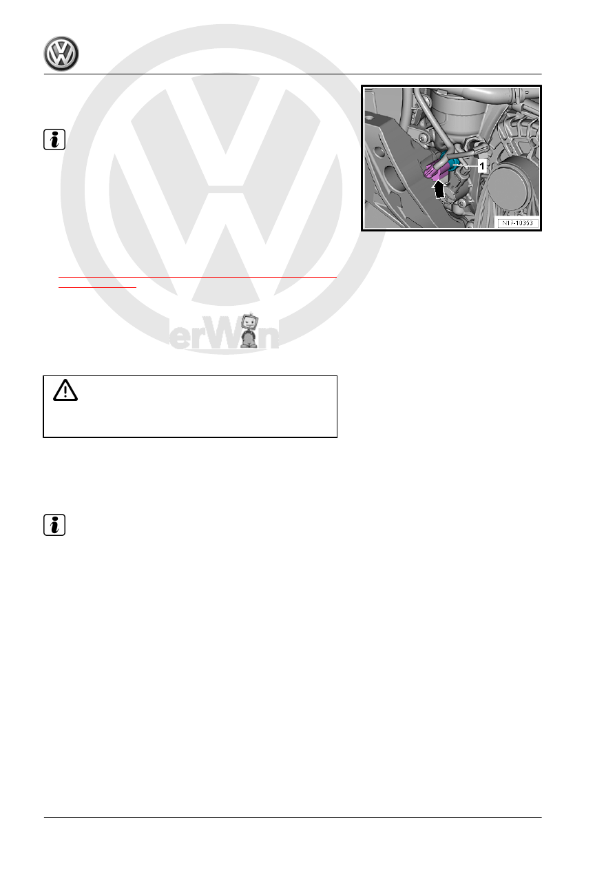
– Remove the Oil Pressure Switch -1-.
Installing

Note

To prevent oil loss, insert the Oil Pressure Switch - F1- in the

opening immediately.

Install in reverse order of removal. Note the following:
– Check the oil level. Refer to ⇒ Maintenance ; Booklet  36.1 ;

Procedure Descriptions; Engine Oil Level, Checking .

Tightening Specifications
♦ Refer to

⇒ “4.2 Overview - Oil Pressure Switch/Oil Pressure Regulator

Valve”, page 198

 .

4.4

Reduced Oil Pressure Switch - F378- ,

Removing and Installing

Special tools and workshop equipment required
♦ Socket and Jointed Extension - 24mm - T40175-

Caution

This procedure contains mandatory replaceable parts. Refer

to component overview prior to starting procedure.

Mandatory Replacement Parts
♦ Seal - Reduced Oil Pressure Switch
Removing

Note

Place a cloth under the accessory assembly bracket to collect

leaking engine oil.

Replace the seal after each time the oil pressure switch is

loosened.

– Disconnect the electrical connector -arrow- on the Reduced

Oil Pressure Switch - F378- .

– Remove the Reduced Oil Pressure Switch -1-.
Installing
Install in reverse order of removal. Note the following:

Note

Insert the Reduced Oil Pressure Switch - F378- immediately to

prevent losing any engine oil.

– Check the oil level. Refer to ⇒ Maintenance ; Booklet  36.1 ;

Procedure Descriptions; Engine Oil Level, Checking .

Tightening Specifications
♦ Refer to

⇒ “4.2 Overview - Oil Pressure Switch/Oil Pressure Regulator

Valve”, page 198

 .

4.5

Oil Pressure Switch, Level 3 - F447- ,

Removing and Installing

Special tools and workshop equipment required
♦ Socket and Jointed Extension - 24mm - T40175-

Caution

This procedure contains mandatory replaceable parts. Refer

to component overview prior to starting procedure.

Mandatory Replacement Parts
♦ Seal - Oil Pressure Switch, Level 3

Note

Replace the seal after each time the oil pressure switch is loos‐

ened.

Removing
– Remove the noise insulation. Refer to ⇒  Body Exterior; Rep.

Gr.  66 ; Noise Insulation; Overview - Noise Insulation .

– Remove the air filter housing. Refer to

⇒ “3.2 Air Filter Housing, Removing and Installing”,

page 294

 .

– Free up the wiring harness -1 and 2- from the air guide pipe.
– Loosen the screw-type clamp -3-.

– Remove the bolts -arrows-, loosen the screw-type clamp and

remove the air guide pipe.

– Disconnect the connector -1- from the Oil Pressure Switch,

Level 3 - F447- .

– Remove the bolts -arrows- and remove the toothed belt cover.

Note

Place a cleaning cloth underneath, to catch oil leaking out.

– Remove the Oil Pressure Switch, Level 3 - F447- -2- using the

Socket and Jointed Extension - 24mm - T40175- .

Installing
Install in reverse order of removal. Note the following:

Note

To prevent coolant loss, install the Oil Pressure Switch, Level 3 -

F447- in the hole immediately.

– Check the oil level. Refer to ⇒ Maintenance ; Booklet  36.1 ;

Procedure Descriptions; Engine Oil Level, Checking .

Tightening Specifications
♦ Refer to

⇒ “4.2 Overview - Oil Pressure Switch/Oil Pressure Regulator

Valve”, page 198

 .

♦ Refer to 

⇒ “3.1 Overview - Air Filter Housing”, page 293

 .

♦ Refer to ⇒  Body Exterior; Rep. Gr.  66 ; Noise Insulation;

Overview - Noise Insulation .

4.6

Oil Pressure, Checking

⇒ “4.6.1 Engine Oil Pressure, Checking”, page 202

 .

⇒ “4.6.2 Piston Spray Nozzles Oil Pressure, Checking”,

page 204

 .

4.6.1

Engine Oil Pressure, Checking

Special tools and workshop equipment required
♦ Oil Pressure Gauge Kit - VAG1342-
♦ Socket and Jointed Extension - 24mm - T40175-
Test Prerequisites
• Oil level OK

• The engine oil temperature at least 80 °C (176 °F) (the coolant

fan must start up once).

Note

The oil pump is regulated and has two pressure stages. The

pressure stages are checked one after the other.

During the break-in phase or in engine emergency running

mode the oil pump only pumps in the higher pressure stage.

The oil pressure depends on the engine oil temperature. At an

engine oil temperature of 80 °C (176 °F) approximately the

average must be reached.

– After installing new parts (engine/partial engine, cylinder head

or turbocharger) limit the oil pressure regulation for approxi‐

mately 1000 km to the higher pressure stage. From this, the

higher friction is taken into account when breaking in new

components, and the optimum removal of particles from the

initial wear in is ensured. To do this connect the vehicle diag‐

nostic tester, switch on the ignition and select the following

menu items:

01 - Engine electronics

Guided functions

01 - Oil Pressure Regulation/Retraction Activating

Test Sequence
– Disconnect the electrical connector -arrow- on the Reduced

Oil Pressure Switch - F378- .

– Place a cloth under the accessory assembly bracket to collect

leaking engine oil.

– Remove the Reduced Oil Pressure Switch - F378- -1-.
– Screw the Oil Pressure Gauge Kit - VAG1342- into the oil filter

bracket in place of the oil pressure switch.

– Push the Reduced Oil Pressure Switch - F378- in the Oil Pres‐

sure Tester and connect the connector.

– Connect the Oil Pressure Tester to the ground.
– Start the engine and check the oil pressure of the specified

RPMs.

• Oil pressure at idle: 0.85 to 1.6 bar (12.3 to 23.2 psi)
• Oil pressure at 2,000 RPM: 1.2 to 1.6 bar (17.4 to 23.2 psi)
• Oil pressure at 3,700 RPM: 1.2 to 1.6 bar (17.4 to 23.2 psi)
– Turn off the engine.
– Remove the noise insulation. Refer to ⇒  Body Exterior; Rep.

Gr.  66 ; Noise Insulation; Overview - Noise Insulation .


Content   ..  689  690  691  692   ..