Volkswagen Golf / Golf GTI / Golf Variant. Manual - part 692


  Index      Volkswagen     Volkswagen Golf / Golf GTI / Golf Variant - service repair manual 2013 year


Search            copyright infringement  


Content   ..  690  691  692  693   ..


Volkswagen Golf / Golf GTI / Golf Variant. Manual - part 692


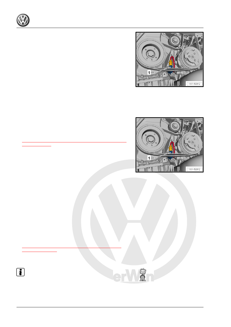
– Remove the connector -1- from the Oil Pressure Regulation

Valve - N428- . Unclip the cable and route downward so that

is not in the belt drive unit. With the connector removed the oil

pump only pumps in the higher pressure stage.

– Start the engine and check the oil pressure of the specified

RPMs.

• Oil pressure at idle: 0.85 to 4.0 bar (12.3 to 43 psi)
• Oil pressure at 2,000 RPM: 2.0 to 2.4 bar (29 to 34.8 psi)
• Oil pressure at 3,700 RPM: 3 to 4 bar (43 to 58 psi)
Assembling
– Install the oil pressure switch.
– Connect the connector -1- to the Oil Pressure Regulation

Valve - N428- . Carefully route the cable.

– Install the noise insulation. Refer to ⇒  Body Exterior; Rep. Gr. 

66 ; Noise Insulation; Overview - Noise Insulation .

– Check the engine control module Diagnostic Trouble Code

(DTC) memory and erase any entries.

Tightening Specifications
♦ Refer to

⇒ “4.2 Overview - Oil Pressure Switch/Oil Pressure Regulator

Valve”, page 198

 .

4.6.2

Piston Spray Nozzles Oil Pressure,

Checking

Special tools and workshop equipment required
♦ Oil Pressure Gauge Kit - VAG1342-
♦ Socket and Jointed Extension - 24mm - T40175-
Test Prerequisites
• Oil level OK
• The engine oil temperature at least 80 °C (176 °F) (the coolant

fan must start up once).

Test Sequence
– Remove the Oil Pressure Switch, Level 3 - F447- . Refer to

⇒ “4.5  Oil Pressure Switch, Level 3 F447 , Removing and

Installing”, page 201

 .

– Install the Oil Pressure Gauge Kit - VAG1342- in place of the

oil pressure switch.

Note

Risk of damaging the oil pressure tester. The hose from the oil

pressure tester must not come in contact with the coolant pump

toothed belt sprocket.

– The threaded hole in the Oil Pressure Gauge Kit - VAG1342-

must be closed. If necessary install the Oil Pressure Switch,

Level 3 - F447- .

– Remove the connector -arrow- from the Piston Cooling Nozzle

Control Valve - N522- . With the connector removed the oil

filler hole to the piston cooling is opened.

– Place the air guide pipe back on the hose connections, so that

the engine can be started.

– Start the engine and check the oil pressure.
• Oil pressure at idle: minimum 0.60 bar (8.7 psi).
Assembling
– Install the oil pressure switch.
Tightening Specifications
♦ Refer to

⇒ “4.2 Overview - Oil Pressure Switch/Oil Pressure Regulator

Valve”, page 198

 .

4.7

Piston Cooling Nozzle Control Valve -

N522- , Removing and Installing

Removing

Caution

This procedure contains mandatory replaceable parts. Refer

to component overview prior to starting procedure.

Mandatory Replacement Parts
♦ Bolt - Piston Cooling Nozzle Control Valve
♦ O-rings - Piston Cooling Nozzle Control Valve

Note

Place a cloth under the accessory assembly bracket to collect

leaking engine oil.

– Disconnect the connector -arrow- from the Piston Cooling

Nozzle Control Valve - N522- .

– Remove the bolt -1- and remove the Piston Cooling Nozzle

Control Valve - N522- -2-.

Installing
Install in reverse order of removal. Note the following:

Note

Replace the O-rings.

To prevent oil loss insert the Piston Cooling Nozzle Control

Valve - N522- immediately in the opening.

– Check the oil level. Refer to ⇒ Maintenance ; Booklet  36.1 ;

Procedure Descriptions; Engine Oil Level, Checking .

Tightening Specifications
♦ Refer to

⇒ “4.2 Overview - Oil Pressure Switch/Oil Pressure Regulator

Valve”, page 198

4.8

Oil Pressure Regulation Valve - N428- ,

Removing and Installing

Special tools and workshop equipment required
♦ Used Oil Collection and Extraction Unit - SMN372500-

Caution

This procedure contains mandatory replaceable parts. Refer

to component overview prior to starting procedure.

Mandatory Replacement Parts
♦ O-ring - Oil Pressure Regulation Valve
♦ Bolt - Oil Pressure Regulation Valve
Removing
– Remove the noise insulation. Refer to ⇒  Body Exterior; Rep.

Gr.  66 ; Noise Insulation; Overview - Noise Insulation .

– Remove the ribbed belt. Refer to

⇒ “1.2 Ribbed Belt, Removing and Installing”, page 46

 .

– Place the Used Oil Collection and Extraction Unit -

SMN372500- under the engine.

– Disconnect the connector -1-.

– Remove the bolt -2- and the Oil Pressure Regulation Valve -

N428- .

Installing
Install in reverse order of removal. Note the following:

Note

Replace the O-ring after removing.

Tightening Specifications
♦ Refer to

⇒ “4.2 Overview - Oil Pressure Switch/Oil Pressure Regulator

Valve”, page 198

♦ Refer to ⇒  Body Exterior; Rep. Gr.  66 ; Noise Insulation;

Overview - Noise Insulation .


Content   ..  690  691  692  693   ..