Volkswagen Golf / Golf GTI / Golf Variant. Manual - part 660


  Index      Volkswagen     Volkswagen Golf / Golf GTI / Golf Variant - service repair manual 2013 year


Search            copyright infringement  


Content   ..  658  659  660  661   ..


Volkswagen Golf / Golf GTI / Golf Variant. Manual - part 660


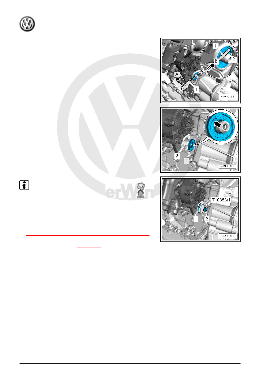
– Pry out the seal in direction of -arrow A-.
– Clean the running and sealing surface.

– Coat the sealing surface of the balance shaft -2- with trans‐

mission oil.

– Push the seal -1- onto the balance shaft.
• “Luftseite” or (“Outside”) -arrow- must be readable from the

outside.

Note

The drive wheel bolt -2- has left-hand thread.

– Mount the Seal Installer, Intermediate Shaft - T10353/1- on the

shaft seal -1- and then tighten it all the way into the cylinder

block with the bolt -2-. Be careful not to tilt the shaft seal when

doing this.

– Install the toothed belt on the coolant pump. Refer to

⇒ “2.8 Coolant Pump Toothed Belt, Removing and Installing”,

page 235

 .

– Fill with coolant. Refer to 

⇒ page 218

 .

5

Piston and Connecting Rod

⇒ “5.1 Overview - Piston and Connecting Rod”, page 77

 .

⇒ “5.2 Pistons, Removing and Installing”, page 78

 .

⇒ “5.3 Pistons and Cylinder Bore, Checking”, page 80

 .

⇒ “5.4 New Connecting Rod, Separating”, page 84

 .

⇒ “5.5 Connecting Rods, Checking Radial Clearance”,

page 84

 .

5.1

Overview - Piston and Connecting Rod

1 - Connecting Rod Bolts

❑ 45 Nm + 90°
❑ Use old bolt to measure

radial play

❑ Lubricate the thread and

contact surface.

❑ Replace after removing

2 - Connecting Rod Bearing

Cap

❑ Pay attention to the in‐

stalled position.

❑ Due to the separation

procedure (cracking) of

the connecting rod, the

connecting rod bearing

cap only fits in one posi‐

tion and only to the cor‐

responding connecting

rod.

❑ Mark affiliation to cylin‐

der -A-

❑ Installed position: the

markings -B- face the

belt pulley side

❑ Disconnect the new

connecting rod. Refer to

⇒ “5.4 New Connecting

Rod, Separating”,

page 84

 .

3 - Bearing Shells

❑ Installed position. Refer

to

⇒ Fig. ““Installed Posi‐

tion of Bearing Shell”“ ,

page 78

❑ Do not interchange used bearing shells (mark)
❑ Coat with oil before installing
❑ Axial play new: 0.10 to 0.35 mm, wear limit: 0.40 mm
❑ Check radial clearance with Plastigage

®

, new: 0.02 to 0.06 mm, wear limit: 0.09 mm. Do not turn crank‐

shaft when checking radial clearance

4 - Relief Valve

❑ 27 Nm

5 - Oil Spray Jet

❑ For piston cooling

6 - Locking Ring

❑ Replace after removing

7 - Piston Pin

❑ Coat with oil before installing

8 - Piston

❑ Removing and installing. Refer to 

⇒ “5.2 Pistons, Removing and Installing”, page 78

 .

❑ Mark installed position and cylinder allocation
❑ Arrow on piston face points toward belt pulley side
❑ Check piston and cylinder bore. Refer to 

⇒ “5.3 Pistons and Cylinder Bore, Checking”, page 80

 .

9 - Compression Rings

❑ Use piston ring pliers (commercially available) for removing and installing
❑ Offset gaps by 120°
❑ Installed Position: “TOP” “R” mark must face up toward piston crown
❑ Ring Gap/Groove Clearance, Checking. Refer to

⇒ “5.3 Pistons and Cylinder Bore, Checking”, page 80

 .

10 - Oil Scraping Ring

❑ Two-part
❑ Install offset gaps by 120° to the neighboring compression ring
❑ The “TOP” or “R” marking must face toward the piston crown.
❑ Checking the ring gap. Refer to 

⇒ “5.3 Pistons and Cylinder Bore, Checking”, page 80

 .

❑ Side clearance cannot be measured.

11 - Connecting Rod

❑ Always replace as a set.
❑ Mark affiliation to cylinder -A-
❑ Installed position: the markings -B- face the belt pulley side
❑ Disconnect the new connecting rod. Refer to 

⇒ “5.4 New Connecting Rod, Separating”, page 84

 .

❑ Radial play, measuring. Refer to 

⇒ “5.5 Connecting Rods, Checking Radial Clearance”, page 84

 .

Installed Position of Bearing Shell
– Place bearing shells centrally into connecting rod and con‐

necting rod bearing cap.

Dimension -a- must be the same at left and right.

5.2

Pistons, Removing and Installing

Special tools and workshop equipment required
♦ Pilot Drift - VW222A-
♦ Piston ring compressor, commercially available

Caution

This procedure contains mandatory replaceable parts. Refer

to component overview prior to starting procedure.

Mandatory Replacement Parts
♦ Bolts - Connecting Rod
♦ Ring - Locking
Removing
– Secure the engine to the Engine And Transmission Holder -

VAS6095- . Refer to

⇒ “1.3 Engine, Securing on Engine and Transmission Holder”,

page 23

 .

– Remove the cylinder head. Refer to

⇒ “1.3 Cylinder Head, Removing and Installing”, page 94

 .

– Remove the oil pan upper section. Refer to

⇒ “1.4 Oil Pan Upper Section, Removing and Installing”, page

185

 .

– Mark the installed position and cylinder allocation.
– Mark installed position and connecting rod cylinder -item 11-

⇒ Item 11 (page 78)

 .

– Remove the connecting rod bearing cap and pull the piston

and connecting rod upward.

Note

Warm the piston to approximately 60 °C (140 °F) if it is difficult to

move the piston pin.

– Remove the locking ring from the eye of the piston bolt.
– Remove the piston pin using the Pilot Drift - VW222A- .
Installing
Install in reverse order of removal. Note the following:

Note

Replace the bolts were tightened with an additional turn.

Arrow on piston face points toward belt pulley side.

Offset the piston ring gap by 120°.

– Coat the contact surfaces on the bearing shells with oil.
– Install the piston with a piston ring compressor. Pay attention

to the installed position -item 8- 

⇒ Item 8 (page 78)

 .

– Install the connecting rod bearing cap. Pay attention to the in‐

stalled position -item 2- 

⇒ Item 2 (page 77)

 .

– Install the cylinder head. Refer to

⇒ “1.3 Cylinder Head, Removing and Installing”, page 94

 .

– Install the oil pan upper section. Refer to

⇒ “1.4 Oil Pan Upper Section, Removing and Installing”, page

185

 .


Content   ..  658  659  660  661   ..