Volkswagen Golf / Golf GTI / Golf Variant. Manual - part 659
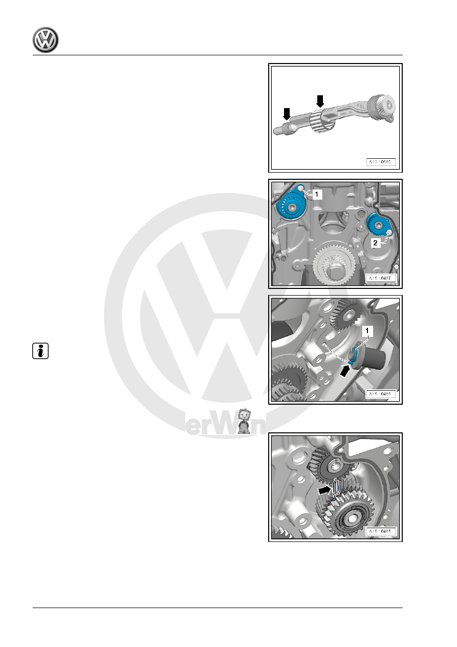
– Lubricate the balance shaft mountings -arrows- with engine
oil.
– Install the intake side balance shaft and tighten the bolt -2-.
– Replace the O-ring -1- and coat with engine oil.
– Coat the mounting pin with engine oil and insert it. The align‐
ment pin -arrow- for the mounting pin must engage in the hole
in the cylinder block.
Note
♦
Always replace the intermediate sprocket. Otherwise the
backlash will not adjust itself and it could result in engine dam‐
age.
♦
The new intermediate sprocket has an anti-friction coating that
wears off after a short period of use, which automatically ad‐
justs the backlash.
– Mark the tooth face on the intermediate sprocket -arrows-.
– Install the intermediate sprocket; the marking on the balance
shaft must be between the markings on the tooth faces.