Volkswagen Golf / Golf GTI / Golf Variant. Manual - part 658


  Index      Volkswagen     Volkswagen Golf / Golf GTI / Golf Variant - service repair manual 2013 year


Search            copyright infringement  


Content   ..  656  657  658  659   ..


Volkswagen Golf / Golf GTI / Golf Variant. Manual - part 658


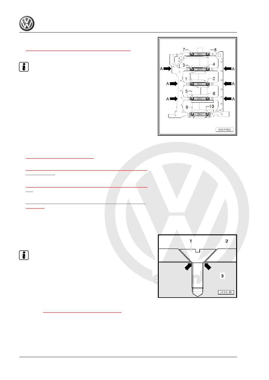
– Install the crankshaft bearing and secure with the old bolts

-1 to 10-. Refer to

⇒ Fig. ““Crankshaft, Tightening Sequence”“ , page 63

 . Do not

turn the crankshaft.

Note

Ignore bolts -arrow A-.

– Remove the crankshaft bearing cap again.
– Compare width of Plastigage

®

 with calibrated scale.

Radial clearance:
• New: 0.017 to 0.037 mm.
• Wear limit: 0.15 mm.

3.7

Sensor Wheel, Removing and Installing

– Removing engine. Refer to

⇒ “1.1 Engine, Removing”, page 8

 .

– Remove the sealing flange on the transmission side. Refer to

⇒ “2.3 Sealing Flange, Removing and Installing, Transmission

Side”, page 59

 .

– Remove the oil pan upper section. Refer to

⇒ “1.4 Oil Pan Upper Section, Removing and Installing”, page

185

 .

– Remove the balance shaft timing chain. Refer to

⇒ “3.4 Balance Shaft Drive Chain, Removing and Installing”,

page 130

– Remove the connecting rod bearing cover.
– Remove the crankshaft bearing cover.
– Remove the crankshaft and the sensor wheel.
– Replace the sensor wheel -2- each time the bolts -1- are loos‐

ened.

Note

After tightening a second time, the attachment point of the

countersunk screws of the sensor wheel are so deformed that

the screw heads lie on the crankshaft -3- -arrows- and the

sensor wheel is loose underneath the screws.

Installation of the sensor wheel is only possible in one position,

the bore holes are shifted.

Tightening Specifications
♦ Refer to 

⇒ “3.1 Overview - Crankshaft”, page 62

 .

4

Balance Shaft

⇒ “4.1 Overview - Balance Shaft”, page 69
⇒ “4.2 Balance Shaft, Removing and Installing”, page 70
⇒ “4.3 Balance Shaft Sealing Ring, Replacing, Intake Side”, page

75

4.1

Overview - Balance Shaft

1 - Bolt

❑ 4 Nm 45°
❑ Replace after removing

2 - Balance Shaft

❑ Exhaust side
❑ Must be replaced after

removing

❑ Lubricate the bearing

with engine oil

❑ Replacing. Refer to

⇒ “4.2.2 Balance Shaft

Exhaust Side, Remov‐

ing and Installing”, page

73

 .

3 - Needle Bearing Rim

❑ Replace the balance

shaft after each remov‐

al.

❑ Install a new needle

bearing with the same

color identification

4 - Pipe for Balance Shaft

❑ Installed position. Refer

to

⇒ Fig. ““Balance Shaft

Pipe - Installed Posi‐

tion”“ , page 70

5 - Cylinder Block
6 - Balance Shaft Seal Intake

Side

❑ Replacing. Refer to

⇒ “4.3 Balance Shaft

Sealing Ring, Replac‐

ing, Intake Side”,

page 75

 .

7 - Balance Shaft

❑ Intake side
❑ Must be replaced after removing
❑ Lubricate the bearing with engine oil
❑ Replacing. Refer to 

⇒ “4.2.1 Balance Shaft Intake Side, Removing and Installing”, page 70

 .

8 - Needle Bearing Rim

❑ Replace the balance shaft after each removal.
❑ Install a new needle bearing with the same color identification

9 - Bolt

❑ 4 Nm 45°
❑ Replace after removing

Balance Shaft Pipe - Installed Position
The openings -arrow- must face the chain side.

4.2

Balance Shaft, Removing and Installing

⇒ “4.2.1 Balance Shaft Intake Side, Removing and Installing”,

page 70

 .

⇒ “4.2.2 Balance Shaft Exhaust Side, Removing and Installing”,

page 73

 .

4.2.1

Balance Shaft Intake Side, Removing

and Installing

Balance shaft and needle bearing must be replaced after every

removal. Install a new needle bearing with the same color identi‐

fication

Caution

This procedure contains mandatory replaceable parts. Refer

to component overview prior to starting procedure.

Mandatory Replacement Parts
♦ Balance Shaft - Intake Side
♦ Bearing - Needle Rim
♦ Bolt - Intake Side Balance Shaft
♦ Bolt - Intermediate Sprocket
♦ O-ring - Intermediate Shaft
♦ Sprocket - Intermediate
Removing
• Engine removed.
– Remove the toothed belt from the coolant pump. Refer to

⇒ “2.8 Coolant Pump Toothed Belt, Removing and Installing”,

page 235

 .

– Remove timing chain upper cover. Refer to

⇒ “2.2.1 Upper Timing Chain Cover, Removing and Installing”,

page 106

 .

– Remove the lower timing chain cover. Refer to

⇒ “2.2.2 Lower Timing Chain Cover, Removing and Installing”,

page 108

 .

– Remove the camshaft timing chain. Refer to

⇒ “3.3 Camshaft Timing Chain, Removing and Installing”,

page 118

 .

– Remove the balance shaft drive chain. Refer to

⇒ “3.4 Balance Shaft Drive Chain, Removing and Installing”,

page 130

 .

– Remove the bolt -2-.
– Remove the drive wheel -1- for the toothed belt from the cool‐

ant pump.

– Remove the intermediate shaft sprocket -1-.

– Remove the bolt -2- for the intake side balance shaft and re‐

move the balance shaft.

Installing


Content   ..  656  657  658  659   ..