Volkswagen Golf / Golf GTI / Golf Variant. Manual - part 656
 

  Index      Volkswagen     Volkswagen Golf / Golf GTI / Golf Variant - service repair manual 2013 year


Search            copyright infringement  


Content   ..  654  655  656  657   ..


Volkswagen Golf / Golf GTI / Golf Variant. Manual - part 656


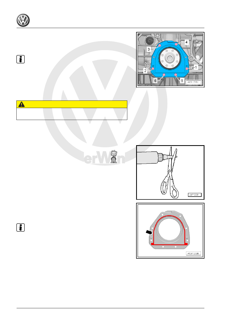
– Remove the bolts -1 through 6-.
– Remove sealing flange.
Installing

Note

♦

Be sure to check the expiration date of the silicone sealant.

♦

The sealing flange must be installed within 5 minutes after ap‐

plication of Silicone Sealant.

♦

To prevent contamination of the lubricating system with seal‐

ant residue, place a clean cloth over the open components of

the oil pan.

CAUTION

Risk of injuring the eyes from sealant residue.
– Wear protective eyewear.

– Remove remaining sealant on the cylinder head with a flat

blade scraper or with a rotating plastic brush.

– Sealing surfaces must be free of oil and grease.

– Cut the tube nozzle at the front marking (nozzle diameter: ap‐

proximately 2 mm).

– Apply silicone sealant as illustrated to the clean sealing sur‐

face of the sealing flange.

♦ Sealant bead thickness: 2 to 3 mm.

Note

♦

The sealing flange must be installed within five minutes after

application of silicon sealant.

♦

The sealant bead may not be thicker than specified, otherwise

excess sealant could enter the oil pan and clog the oil intake

tube.

– Position the Seal Installer - Sealing Flange Guide Sleeve -

T20097- on the crankshaft pins -A-.

– Lightly coat the seal with engine oil.
– Slide the sealing flange onto the crankshaft pins with the Seal

Installer - Sealing Flange Guide Sleeve - T20097- .

– Tighten the new bolts in evenly in the sequence shown:

Step

Bolts

Tightening Specification/Additional

Turn

1.

-1 to 6-

Install all the way in by hand.

2.

-1 to 6-

9 Nm

Note

♦

Only six bolts are installed, two bolt openings remain open.

♦

After installing sealing flange, the sealant must dry for approx‐

imately 30 minutes. Only after then may the engine oil be

replenished.

Assemble in reverse order of disassembly.
Tightening Specifications
♦ Refer to

⇒ “2.1 Overview - Cylinder Block, Transmission Side”,

page 57

 .

3

Crankshaft

⇒ “3.1 Overview - Crankshaft”, page 62
⇒ “3.2 Crankshaft Dimensions”, page 64
⇒ “3.3 Main Bearing Shells Allocation”, page 64
⇒ “3.4 Crankshaft Needle Bearing, Replacing”, page 65
⇒ “3.5 Crankshaft, Measuring Axial Clearance”, page 67
⇒ “3.6 Crankshaft, Measuring Radial Clearance”, page 67
⇒ “3.7 Sensor Wheel, Removing and Installing”, page 68

3.1

Overview - Crankshaft

Note

Secure the engine to the assembly stand using the Engine and

Gearbox Bracket - VAS6095A- when performing the assembly

work. Refer to

⇒ “1.3 Engine, Securing on Engine and Transmission Holder”,

page 23

 .

1 - Cylinder Block
2 - Bearing Shell for Cylinder

Block

❑ With lubricating groove
❑ Lubricate
❑ Do not interchange

used bearing shells

(mark)

❑ Crankshaft bearing

shells identification

(classification). Refer to

⇒ “3.3 Main Bearing

Shells Allocation”,

page 64

 .

3 - Crankshaft

❑ After removal, lay aside

so that sensor wheel

-item 8-

⇒ Item 8 (page 63)

 is

not rested on and be‐

comes damaged

❑ If the crankshaft is being

replaced, then the bear‐

ing shells must be allo‐

cated to the bearing

cover. Refer to

⇒ “3.3 Main Bearing

Shells Allocation”,

page 64

 .

❑ Axial clearance. Refer

to

⇒ “3.5 Crankshaft,

Measuring Axial Clear‐

ance”, page 67

 .

❑ Radial clearance. Refer

to

⇒ “3.6 Crankshaft,

Measuring Radial Clearance”, page 67

 .

❑ Do not turn crankshaft when measuring radial play
❑ Crankshaft dimensions. Refer to 

⇒ “3.2 Crankshaft Dimensions”, page 64

 .

4 - Bearing Shell for Bearing Cap

❑ Without lubricating groove
❑ Lubricate
❑ Do not interchange used bearing shells (mark)
❑ Crankshaft bearing shells identification (classification). Refer to

⇒ “3.3 Main Bearing Shells Allocation”, page 64

 .

5 - Bolt

❑ Replace after removing
❑ Tightening sequence. Refer to 

⇒ Fig. ““Crankshaft, Tightening Sequence”“ , page 63

6 - Bearing Cap

❑ Bearing cap 1: belt pulley side
❑ Retaining tabs of bearing shells and cylinder block/bearing caps must lie above one another

7 - Bolt

❑ 10 Nm + 90°
❑ Replace after removing
❑ Replace sensor wheel every time bolts are loosened. Refer to

⇒ “3.7 Sensor Wheel, Removing and Installing”, page 68

 .

8 - Sensor Wheel

❑ For Engine Speed Sensor - G28-
❑ It is possible to install in one position only, the holes are offset.
❑ Replace sensor wheel every time bolts are loosened
❑ Removing and installing. Refer to 

⇒ “3.7 Sensor Wheel, Removing and Installing”, page 68

 .

9 - Thrust Washers

❑ For bearing 3
❑ Lubricate

10 - Bolt

❑ Replace after removing
❑ Tightening sequence. Refer to 

⇒ Fig. ““Crankshaft, Tightening Sequence”“ , page 63

Crankshaft, Tightening Sequence
– Tighten the crankshaft bolts in the sequence -1 to 10- and

-arrow A- as follows.

Step

Bolts

Tightening Specification/Addi‐

tional Turn

1.

-1- through -10- and

-arrows A-

Install hand-tight

2.

-1- through -10-

65 Nm

3.

-1- through -10-

Turn an additional 90°

4.

-A arrows-

20 Nm

5.

-A arrows-

Turn an additional 90°


Content   ..  654  655  656  657   ..