Volkswagen Golf / Golf GTI / Golf Variant. Manual - part 649
 

  Index      Volkswagen     Volkswagen Golf / Golf GTI / Golf Variant - service repair manual 2013 year


Search            copyright infringement  


Content   ..  647  648  649  650   ..


Volkswagen Golf / Golf GTI / Golf Variant. Manual - part 649


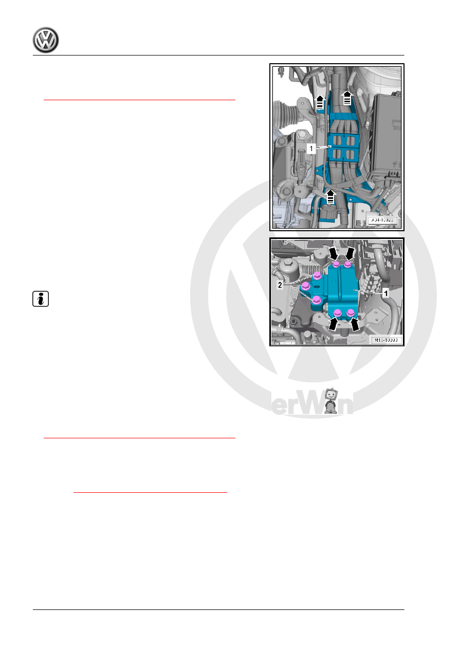
– Unclip the wiring guide -1- upward and move it slightly to the

side in direction of -arrows-.

– Support the engine in its installed position. Refer to

⇒ “2.5 Engine, Supporting in Installed Position”, page 33

 .

– Remove the bolts -2-, then the bolts -arrows- and remove the

transmission mount -1-.

Installing
Install in reverse order of removal. Note the following:

Note

♦

Replace the bolts which have been tightened to torque.

♦

The transmission support and the transmission mount support

arm must be absolutely parallel to each other before installing

bolts. Push the transmission up using a floor jack if necessary.

– Secure the transmission support to the longitudinal member.
– Pull the transmission up using the spindle on the engine sup‐

port bridge until the transmission support touches the trans‐

mission mount support arm.

– Install bolts by hand pay attention while doing so that the bolts

are not installed crooked.

– Check the adjustment of the assembly mounts. Refer to

⇒ “2.7 Subframe Mount, Checking Adjustment”, page 37

 .

– When the bolts are tightened to the tightening specification,

remove the Engine Support Bridge - 10-222A- from the en‐

gine.

Tightening Specifications
♦ Refer to 

⇒ “2.1 Overview - Subframe Mount”, page 29

♦ Refer to ⇒  Electrical Equipment; Rep. Gr.  27 ; Battery; Over‐

view - Battery .

2.4

Pendulum Support, Removing and In‐

stalling

Removing

Caution

This procedure contains mandatory replaceable parts. Refer

to component overview prior to starting procedure.

Mandatory Replacement Parts
♦ Bolts - Pendulum Support
– Remove the noise insulation. Refer to ⇒  Body Exterior; Rep.

Gr.  66 ; Noise Insulation; Overview - Noise Insulation .

– Remove the bolts -1, 2 and 3- and remove pendulum support.
Installing
Install in reverse order of removal. Note the following:
Tightening Specifications

Step

Bolts

Tightening Specification/Additional Turn

1.

-2 and 3-

50 Nm

2.

-1-

130 Nm

3.

-1 to 3-

Turn an additional 90°

♦ Refer to ⇒  Body Exterior; Rep. Gr.  66 ; Noise Insulation;

Overview - Noise Insulation .

2.5

Engine, Supporting in Installed Position

Special tools and workshop equipment required
♦ Engine Support Bridge - 10-222A-
♦ Engine Support Bridge - Engine Support 18 - 10-222A/18-
♦ Engine Support Bridge - Engine Support 29 - 10-222A/29-
♦ Engine Support - Basic Set Square Pipe - T40091/1- and En‐

gine Support - Movable Joint - T40091/3- from the Engine

Support - Basic Set - T40091-

♦ Engine Support Brackets - T40093/3- and Engine Support

Brackets - T40091/3-6- from the Engine Support - Supplement

Kit - T40093A-

♦ Engine Support Bridge - Special Hook (2 pc.) - 10-222A/20-
♦ Engine/Gearbox Support Shackle (2 pc.) - 10-222A/12-

Tool Development
– If the adapter for Engine Support Bridge - Engine Support 4 -

10-222A/4- does not have the indicated holes -arrow- shown

they must be added.

• Dimension -a- = 225 mm.
• Hole diameter = 12.5 mm
– Remove the engine cover. Refer to

⇒ “3.1 Engine Cover, Removing and Installing”, page 38

 .

– Unlock the retaining tab in direction of -arrow-, remove the left

engine cover mount -1-.

– Unclip the right mount -1- for the engine cover from the bracket

-2-.

– Place the Engine Support Bridge - Engine Support 29 -

10-222A/29- on both sides of the vehicle between the fender

bolting edge and the fender bolting plate underneath.

♦ Installed position:
“L” = -1- Adapter is Installed on the “Right” Side of the Vehicle

( Adapter Lock in the Opening on the Fender)

“R” (Not Illustrated), Adapter is Installed on the “Left” Side of the

Vehicle.
The arrow -2- always points in direction of travel.

– Push the Engine Support Bridge - Engine Support 18 -

10-222A/18- and two Engine Support - Movable Joint -

T40091/3- on the Engine Support Bridge - 10-222A- .

– Tighten the Engine Support Bridge - 10-222A- on the Engine

Support Bridge - Engine Support 29 - 10-222A/29- .

– Remove the windshield washer system washer fluid reservoir

filler tube. Refer to ⇒  Electrical Equipment; Rep. Gr.  92 ;

Windshield Washer System; Washer Fluid Reservoir, Remov‐

ing and Installing .

– If equipped remove the wire from the front area of the base of

the longitudinal member -arrow-. Do not disconnect the wiring

harness.

– Place the Engine Support Brackets - T40093/3-6- on both

sides of the longitudinal member the right longitudinal member

is shown here).

– If necessary carefully unclip the Air Conditioning (A/C) system

pipe in the front area. Do not disconnect the wiring harness.

Refer to ⇒  Heating, Ventilation and Air Conditioning; Rep. Gr. 

87 ; Refrigerant Circuit; System Overview - Refrigerant Cir‐

cuit .

• Lock the Engine Support Brackets - T40093/3-6- with the pin

-A- behind the edge of the longitudinal member -arrow-.

– Install the Engine Support Bracket - T40093/3- .
– Connect the Engine Support Brackets - T40093/3- over the

Engine Support - Basic Set - Square Pipe - T40091/1- with the

Engine Support Bridge - 10-222A- and tension.

– Engage the Brackets in the engine lifting eye over the Engine

Support Bridge - Special Hook (2 pc.) - 10-222A/20- and if

necessary over the Engine/Gearbox Support Shackle (2 pc.)

- 10-222A/12- .

– Lightly tension the engine/transmission assembly and Extrac‐

tor via the Brackets .


Content   ..  647  648  649  650   ..