Volkswagen Golf / Golf GTI / Golf Variant. Manual - part 634


  Index      Volkswagen     Volkswagen Golf / Golf GTI / Golf Variant - service repair manual 2013 year


Search            copyright infringement  


Content   ..  632  633  634  635   ..


Volkswagen Golf / Golf GTI / Golf Variant. Manual - part 634


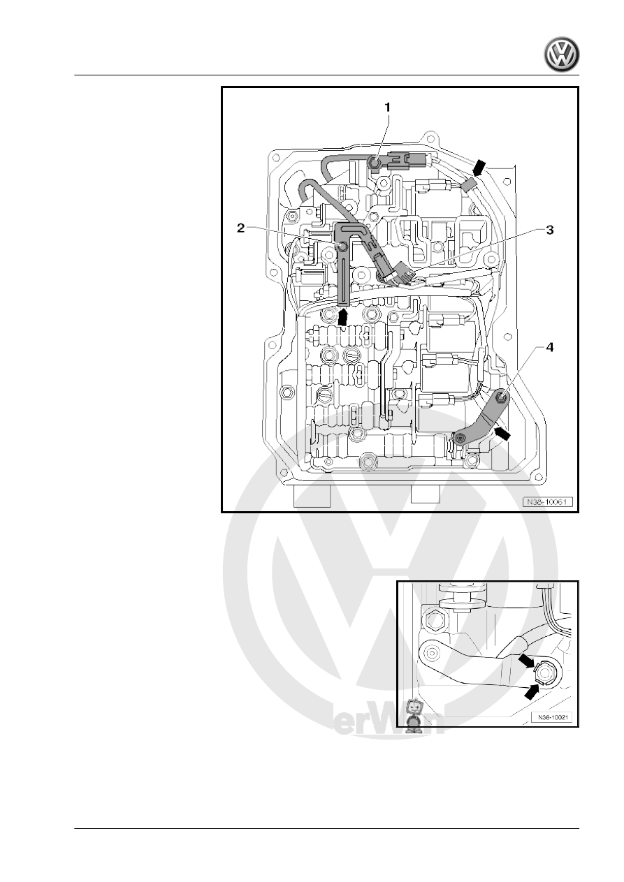
– Remove the Transmission Fluid Temperature Sensor - G93-

-3- from the valve body.

– Disengage the wiring harnesses from the brackets -arrows-.
– If equipped, bend back the locking plate on the selector lever

-arrows-.

– Remove the selector lever -1- from the selector shaft.
– When doing this, hold the selector lever -1- secure with pliers

-2- so that it does not turn when removing the Multifunction

Transmission Range Switch - F125- .

– Make sure the slide -3- on the valve body in which the shift

lever engages is not damaged.

The valve is very »sensitive«. Even minor damage leads to mal‐

function.
– Always slide the valve into the body, secure it against falling

out and never exchange it.

The valve body bolts on the transmission housing have different

lengths and must be replaced.
Only the bolts marked -arrows-, -A arrows- and -B arrows- can be

loosened.

Caution

When loosening the other bolts, the function of the valve body

can be influenced or the valve body splits up.

– Remove the bracket -1 and 2-.
– Loosen the valve body bolts -arrows-,

-arrows A and arrows B- diagonally and then remove the valve

body.

-3- Valve body description, for example, A2

– When removing the valve body, pay attention to the damper

pistons -2-.

– Remove the damper piston -2- with spring.
Installing
– Observe correct routing of wires so that they do not get jam‐

med when installing the valve body.

– Route the wiring harness -5- into the transmission as illustra‐

ted.

The distance -a- must be maintained so that the wiring harness

-5- does not touch the planetary gear and get damaged when the

vehicle is being driven.
– The wiring harnesses -1, 3, 4 and 5- lay over the edge of the

transmission as illustrated.

– Attach the wiring harnesses to the transmission with tape.
– Coat the damper piston -2- with ATF and then install it with the

spring into the transmission housing, as illustrated.

– Mount the valve body and install the two bolts hand-tight.
• The wiring harnesses -1, 3, 4 and 5- must not get caught by

the valve body.

Bolt Lengths and Locations on the Valve Body

Bolts -arrows-

Quantity 6,

M6×21

Bolts -arrows A-

Quantity 2, M6 x

16

Bolts -arrows B-

Quantity 4, M6 x

28

– Install the remaining new bolts and the bracket -1 and 2- and

tighten hand-tight.

Note

If the wires are too short to connect to the sensor or to be

attached to the valve body, then they were routed incorrectly

or they are caught by the valve body. The valve body must be

removed again and wires must be routed correctly.

Replace the valve body bolts.

– Attach the valve body from the inside toward the outside di‐

agonally; tightening specification. Refer to 

⇒ page 89

 .

– Install the Transmission Fluid Temperature Sensor - G93- .

For the tightening specification. Refer to 

⇒ page 89

 .

– Connect the 8-pin connector according to the markings made

on the solenoid valves. Refer to

⇒ “2.3 Wire Routing, Connectors and Bracket on Valve Body”,

page 97

 .

Caution

Confusing the connectors could cause damage to the trans‐

mission.
The wiring harness or the valve body with the solenoid valves

must be replaced if the one of the connectors gets damaged.

– Connect the bracket for the connectors. Refer to

⇒ page 98

 , tightening specification. Refer to 

⇒ page 89

 .

– Connect the connectors -item A- 

⇒ Item A (page 98)

 and

-item B- 

⇒ Item B (page 98)

 .

– Engage the wiring harness -3- in the bracket -7- -arrow B-.
– Attach the selector lever -2- to the selector shaft -6-.
When doing this, make sure the pin on the selector lever -2- en‐

gages into the slider -1- -arrow A-. The slider must be positioned

accordingly if necessary.
– Install the washer -5- and nut -4- on the selector shaft -6-.
The collar on the nut must always face the washer and fit into the

washer when the nut is tightened.
The wiring harness must be routed underneath the selector shaft

lever.


Content   ..  632  633  634  635   ..