Volkswagen Golf / Golf GTI / Golf Variant. Manual - part 635


  Index      Volkswagen     Volkswagen Golf / Golf GTI / Golf Variant - service repair manual 2013 year


Search            copyright infringement  


Content   ..  633  634  635  636   ..


Volkswagen Golf / Golf GTI / Golf Variant. Manual - part 635


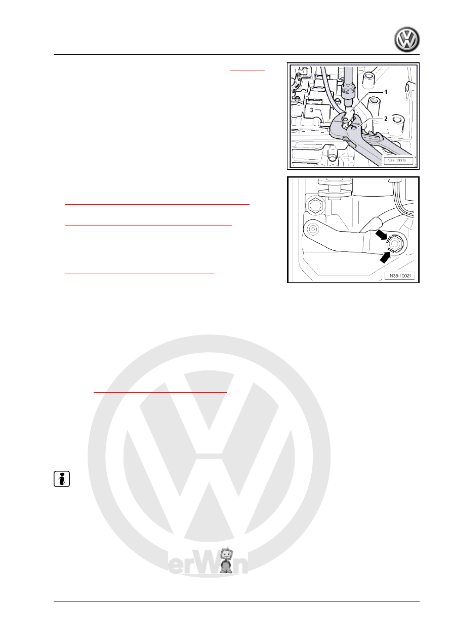
– Tighten the nut on the selector lever -1-. Refer to 

⇒ page 89

 .

– When doing this, hold the selector lever -1- secure with pliers

-2- so that it does not turn when removing the Multifunction

Transmission Range Switch - F125- .

– Make sure the slide -3- on the valve body in which the shift

lever engages is not damaged.

– Bend up the locking plate at the nuts -arrows-, if equipped.
– Install the ATF strainer. Refer to

⇒ “1.2 ATF Strainer, Removing and Installing”, page 86

 .

– Install the ATF pan. Refer to

⇒ “1.1 Oil Pan, Removing and Installing”, page 84

 .

– Connect the battery Ground (GND) cable. Refer to ⇒  Electrical

Equipment; Rep. Gr.  27 ; Battery; Battery, Disconnecting and

Connecting .

– Fill the ATF and check the level. Refer to

⇒ “7 Automatic Transmission Fluid”, page 73

 .

– Connect, for example the Vehicle Diagnostic Tester and select

“function/component selection”.

– Press “drive (Repair Groups 01; 10 through 26 and

28 through 39)”.

– After that “6-speed automatic transmission 09G”.
– Press “01 - OBD”.
– Press “Functions”.
– Press “basic setting”.
Tightening Specifications
♦ Refer to 

⇒ “2.1 Overview - Valve Body”, page 87

2.3

Wire Routing, Connectors and Bracket

on Valve Body

In this chapter the information regarding working on the solenoid

valves is shown in illustrations.
Wiring Routing and Connectors

Note

Mark the solenoid valve and/or sensor and its connector before disconnecting them.

1 - Solenoid Valve 4 - N91-

❑ Wiring colors to the

valve: green/brown

2 - Solenoid Valve 6 - N93-

❑ Wiring colors to the

valve: green/gray

3 - Solenoid Valve 5 - N92-

❑ Wiring colors to the

valve: yellow/purple

4 - Solenoid Valve 9 - N282-

❑ Wiring colors to the

valve: red/blue

5 - Solenoid Valve 10 - N283-

❑ Wiring colors to the

valve: white/black

6 - Solenoid Valve 3 - N90-

❑ Wiring colors to the

valve: green/blue

7 - Solenoid Valve 1 - N88-

❑ Wire color to the valve:

white

8 - Solenoid Valve 2 - N89-

❑ Wire color to the valve:

black

A - Transmission Output

Speed Sensor - G195- Con‐

nector

❑ Wire color to the sensor:

blue/orange

B - Transmission Input Speed

Sensor - G182- Connector

❑ Wire colors to the sensor: white/red

Bracket for Connectors, Securing the Wires

Note

The -arrows- in the illustration point to the wire brackets or the secured wires.

1 - Bracket for the Transmis‐

sion Output Speed Sensor -

G195- Connector

❑ Tightening specifica‐

tion. Refer to

⇒ page 89

 .

2 - Bracket for the Transmis‐

sion Input Speed Sensor -

G182- Connector

❑ Tightening specifica‐

tion. Refer to

⇒ page 89

 .

3 - Transmission Fluid Tem‐

perature Sensor - G93-

❑ Wire colors on the sen‐

sor: orange/orange

4 - Selector Lever
Tightening specification. Refer

to 

⇒ page 89

 .

2.4

Solenoid Valve and Sensor Wiring Har‐

ness, Removing and Installing

⇒ “2.4.1 Wiring Harness, Removing and Installing, Solenoid

Valves”, page 99
⇒ “2.4.2 Wiring Harness, Removing and Installing, Sensors”,

page 100

2.4.1

Wiring Harness, Removing and Instal‐

ling, Solenoid Valves

Caution

This procedure contains mandatory replaceable parts. Refer

to component overview prior to starting procedure.

Mandatory Replacement Parts
♦ O-ring - 14-Pin Transmission Connector
– Drain the ATF. Refer to

⇒ “7.2 ATF, Draining and Filling”, page 76

 .

– Remove the ATF pan. Refer to

⇒ “1.1 Oil Pan, Removing and Installing”, page 84

 .

– Remove the ATF strainer. Refer to

⇒ “1.2 ATF Strainer, Removing and Installing”, page 86

 .

– Remove the valve body. Refer to

⇒ “2.2 Valve Body, Removing and Installing”, page 90

 .

– Disconnect the solenoid valve connector -2- from the trans‐

mission connector.

– Remove the bolt from the 14-pin transmission connector.
– Remove the transmission connector with the wiring harness

outward from the transmission housing.

Install in reverse order of removal. Note the following:
– Replace the O-ring on the transmission connector.
– Coat the O-ring with ATF.
– Push the transmission connector with a new O-ring all the way

into the transmission.

– Tighten the bolt for the 14-pin transmission connector. For the

correct tightening specification. Refer to 

⇒ page 89

 .

– Install the valve body. Refer to 

⇒ page 95

 .

– Install the ATF strainer. Refer to

⇒ “1.2 ATF Strainer, Removing and Installing”, page 86

 .

– Install the ATF pan. Refer to

⇒ “1.1 Oil Pan, Removing and Installing”, page 84

 .

– Fill the ATF and check the level. Refer to

⇒ “7 Automatic Transmission Fluid”, page 73

 .

2.4.2

Wiring Harness, Removing and Instal‐

ling, Sensors

Caution

This procedure contains mandatory replaceable parts. Refer

to component overview prior to starting procedure.

Mandatory Replacement Parts
♦ O-ring - 8-Pin Transmission Connector
– Drain the ATF. Refer to

⇒ “7.2 ATF, Draining and Filling”, page 76

 .

– Remove the ATF pan. Refer to

⇒ “1.1 Oil Pan, Removing and Installing”, page 84

 .

– Remove the ATF strainer. Refer to

⇒ “1.2 ATF Strainer, Removing and Installing”, page 86

 .

– Remove the valve body. Refer to

⇒ “2.2 Valve Body, Removing and Installing”, page 90

 .


Content   ..  633  634  635  636   ..