Volkswagen Golf / Golf GTI / Golf Variant. Manual - part 632


  Index      Volkswagen     Volkswagen Golf / Golf GTI / Golf Variant - service repair manual 2013 year


Search            copyright infringement  


Content   ..  630  631  632  633   ..


Volkswagen Golf / Golf GTI / Golf Variant. Manual - part 632


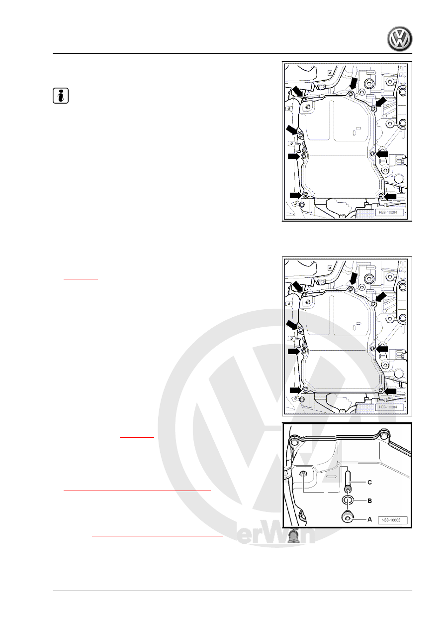
– Loosen and tighten the bolts on the ATF pan -arrows- diago‐

nally.

Note

Some residual ATF will remain in the ATF pan.

– Remove the ATF pan and gasket.
Installing
Install in reverse order of removal. Note the following:
– Clean the two magnets in the ATF pan depressions. Make

sure the magnets touch the ATF pan completely.

– Check the seal for damage and make sure all of the spacers

(quantity: 8) are present.

Otherwise, replace the seal.
– Install the ATF pan and seal; when doing this be sure not to

pinch any lines.

– Make sure the ATF pan seal fits correctly.

– Tighten the ATF pan bolts -arrows- diagonally and in several

steps. For the correct tightening specification. Refer to

⇒ page 89

 .

– Install the overflow pipe -C-. For the correct tightening speci‐

fication. Refer to 

⇒ page 89

 .

– Replace the gasket -B- for the ATF check plug -A-.
– Install the ATF check plug -A- and new gasket -B- hand-tight

only.

– Fill the ATF and check the level. Refer to

⇒ “7 Automatic Transmission Fluid”, page 73

 .

– Install the noise insulation. Refer to ⇒  Body Exterior; Rep. Gr. 

66 ; Noise Insulation; Overview - Noise Insulation .

Tightening Specifications
♦ Refer to 

⇒ “2.1 Overview - Valve Body”, page 87

1.2

ATF Strainer, Removing and Installing

Removing
– Remove the ATF pan. Refer to

⇒ “1.1 Oil Pan, Removing and Installing”, page 84

 .

– Remove the bolts -arrows- from the ATF strainer.
– Remove the ATF strainer -A- from the valve body.
Installing
– Lightly coat the seals on the ATF strainer suction collar with

ATF.

– Replace the ATF strainer if the seals are loose or faulty.

– Mount the ATF strainer -A- on the valve body and tighten the

bolts -arrows-. For the correct tightening specification. Refer

to 

⇒ page 89

 .

– Install the ATF pan. Refer to

⇒ “1.1 Oil Pan, Removing and Installing”, page 84

 .

– Fill the ATF and check the level. Refer to

⇒ “7 Automatic Transmission Fluid”, page 73

 .

Tightening Specifications
♦ Refer to 

⇒ “2.1 Overview - Valve Body”, page 87

2

Valve Body

⇒ “2.1 Overview - Valve Body”, page 87
⇒ “2.2 Valve Body, Removing and Installing”, page 90
⇒ “2.3 Wire Routing, Connectors and Bracket on Valve Body”,

page 97
⇒ “2.4 Solenoid Valve and Sensor Wiring Harness, Removing and

Installing”, page 99
⇒ “2.5  Transmission Input Speed Sensor G182 , Removing and

Installing”, page 101
⇒ “2.6  Transmission Output Speed Sensor G195 , Removing and

Installing”, page 101

2.1

Overview - Valve Body

1 - ATF Check Plug

❑ 27 Nm
❑ ATF level, checking and

filling. Refer to

⇒ “7 Automatic Trans‐

mission Fluid”,

page 73

 .

2 - Seal

❑ Replace after removing

3 - Overflow Pipe

❑ 2 Nm
❑ Remove in order to

drain the ATF

4 - Oil Pan

❑ Removing and instal‐

ling. Refer to

⇒ “1.1 Oil Pan, Remov‐

ing and Installing”, page

84

 .

5 - Bolt

❑ 7 Nm
❑ Tighten the ATF pan

bolts diagonally and in

several steps.

6 - Seal

❑ With spacers (quantity:

8)

❑ Check before installing
❑ Replace brittle, cracked

or deformed seals

7 - Magnet

❑ Quantity: 2; in depres‐

sions in the ATF pan

❑ Clean before installing the ATF pan.

8 - Bolt

❑ 8 Nm +90°
❑ Replace after removing

❑ For attaching the valve body to the transmission
❑ Quantity 12; with different lengths 

⇒ Fig. ““Bolt Lengths and Locations on the Valve Body”“ , page 96

9 - Bolt

❑ 11 Nm
❑ Quantity: 3
❑ For attaching the ATF strainer to the valve body

10 - Oil Screen

❑ Removing and installing. Refer to 

⇒ “1.2 ATF Strainer, Removing and Installing”, page 86

 .

11 - Valve Body

❑ Removing and installing. Refer to 

⇒ “2.2 Valve Body, Removing and Installing”, page 90

 .

❑ Solenoid valve identification. Refer to

⇒ “2.3 Wire Routing, Connectors and Bracket on Valve Body”, page 97

 .

❑ Allocation. Refer to the Parts Catalog.

12 - Bolt

❑ 7 Nm

13 - Bolt

❑ 6 Nm

14 - Transmission Input Speed Sensor - G182-

❑ Removing and installing. Refer to

⇒ “2.5  Transmission Input Speed Sensor G182 , Removing and Installing”, page 101

 .

15 - Bolt

❑ 7 Nm

16 - Transmission Output Speed Sensor - G195-

❑ Removing and installing. Refer to

⇒ “2.6  Transmission Output Speed Sensor G195 , Removing and Installing”, page 101

 .

17 - Transmission Housing

❑ Illustrated here without the ATF cooler

18 - Bleed Cap
19 - Multifunction Transmission Range Switch - F125-

❑ Removing and installing. Refer to 

⇒ “2.9 Multifunction Switch, Removing and Installing”, page 37

 .

❑ Adjusting. Refer to 

⇒ “2.10 Multifunction Transmission Range Switch, Adjusting”, page 40

 .

20 - Transmission Fluid Temperature Sensor - G93-

❑ Integrated inside the wiring harness -item 23- 

⇒ Item 23 (page 88)

❑ Removing and installing. Refer to

⇒ “2.4.2 Wiring Harness, Removing and Installing, Sensors”, page 100

 .

❑ Wire routing. Refer to 

⇒ “2.3 Wire Routing, Connectors and Bracket on Valve Body”, page 97

21 - Bolt

❑ 6 Nm

22 - Bolt

❑ 6 Nm

23 - Sensor Wiring Harness

❑ With an 8-pin connector
❑ With an O-ring on the connector; always replace the O-ring
❑ With Transmission Fluid Temperature Sensor - G93-
❑ For the Transmission Input Speed Sensor - G182-
❑ For the Transmission Output Speed Sensor - G195-
❑ Removing and installing. Refer to

⇒ “2.4.2 Wiring Harness, Removing and Installing, Sensors”, page 100

 .


Content   ..  630  631  632  633   ..