Volkswagen Golf / Golf GTI / Golf Variant. Manual - part 615


  Index      Volkswagen     Volkswagen Golf / Golf GTI / Golf Variant - service repair manual 2013 year


Search            copyright infringement  


Content   ..  613  614  615  616   ..


Volkswagen Golf / Golf GTI / Golf Variant. Manual - part 615


2

Special Tools

Special tools and workshop equipment required
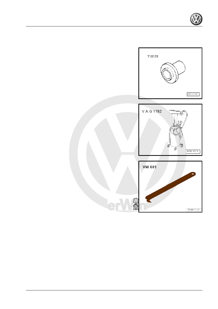
♦ Seal Installer - Torque Converter Seal - T10175-

♦ Used Oil Collection and Extraction Unit - SMN372500-

♦ Puller - Seal Lever - VW681-

37 – Controls, Housing

1

Vehicle Diagnostic Tester , Connect‐

ing

Special tools and workshop equipment required
♦ Vehicle Diagnostic Tester
Volkswagen offers various testers, for example:
♦ Tester - VAS5051/11A-
The operation of these »devices« is described in the respective

operating instructions.
Vehicle Diagnostic Tester Connecting to the Data Link Connector

(DLC).

WARNING

♦ During a test drive you must always secure testing and

measuring equipment on the back seat.

♦ Only the passenger may use the equipment during the

road test.

– Turn on the Vehicle Diagnostic Tester .
The Vehicle Diagnostic Tester is ready for use when it is possible

to select between the fields/buttons 

Guided Functions

 and

Guided Functions

 on the »right« side of the screen.

Depending on equipment and tester version, additional functions

may be »displayed«, for example:

ElsaWin

Test Instruments

On Board Diagnostics (OBD)

»Tester« is Ready for Operation.
– Turn on the ignition.
– Touch a field/button on the display to start desired function.

1 - Shift Cover with Handle

❑ Do not remove the han‐

dle unnecessarily. Un‐

clip only the cover for

the emergency release.

Refer to

⇒ “2.5 Emergency Re‐

lease from P”,

page 32

 .

❑ Removing and instal‐

ling. Refer to

⇒ “2.6 Selector Lever

Handle, Removing and

Installing”, page 33

 .

2 - Selector Mechanism

❑ With integrated Selector

Lever Sensor System

Control Module - J587-

with Selector Lever -

E313- , Tiptronic Switch

- F189- , Selector Lever

Park Position Lock

Switch - F319- and Shift

Lock Solenoid - N110-

❑ Do not grease the selec‐

tor lever cable.

❑ Removing and instal‐

ling. Refer to

⇒ “2.2 Selector Mecha‐

nism, Removing and In‐

stalling”, page 21

 .

❑ Checking and Adjust‐

ing. Refer to

⇒ “2.4 Selector Lever

Cable, Checking and

Adjusting”, page 30

 .

3 - Bolt

❑ 4 Nm
❑ For attaching the selector mechanism to the selector housing
❑ Quantity: 4

4 - Plugs
5 - Nut with Collar

❑ M6 - 8 Nm
❑ M8 - 20 Nm
❑ Quantity: 4

6 - Selector Housing
7 - Clip

❑ For the selector lever cable on the bracket
❑ Is secured to the ATF cooler

8 - Transmission
9 - Cable Mounting Bracket

❑ For selector lever cable
❑ With installed grommet and spacer for the cable mounting bracket on the transmission

10 - Bolt

❑ 13 Nm
❑ Selector lever cable adjusting screw


Content   ..  613  614  615  616   ..