Volkswagen Golf / Golf GTI / Golf Variant. Manual - part 584
5th Gear, Removing Separately
– Cover the openings in the transmission housing with a cloth.
– Move the shift fork -1- into neutral.
– Remove the bolt -2- with the shift jaw for 5th gear.
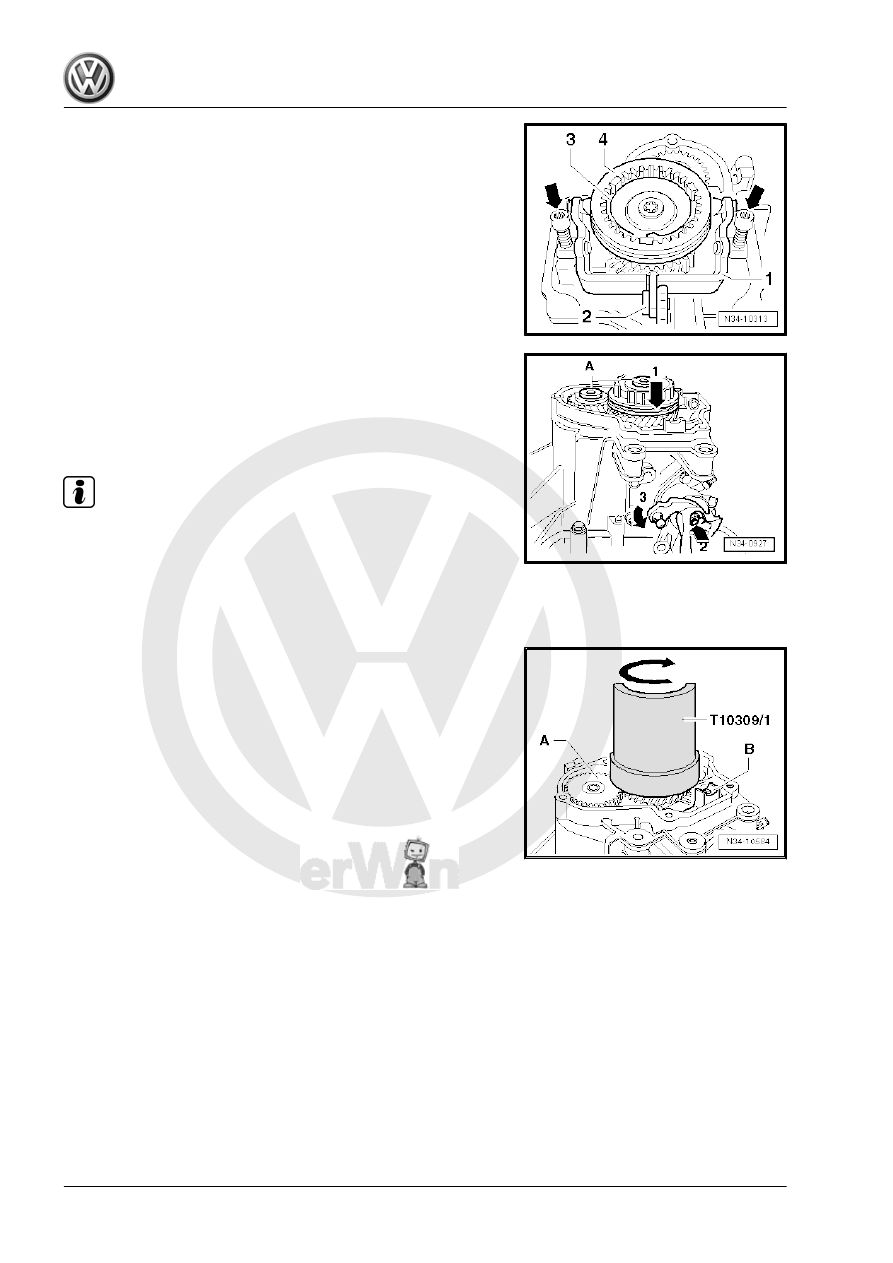
– Remove both bolts -arrows- for the pivot pin.
– Remove the pivot pin.
– Remove the 5th gear shift fork.
– It is not necessary to remove the spring -3- and the locking
collar -4-.
– Remove the bolts -A- for the synchronizer hub and for the 5th
gear wheel. Do this by engaging 5th gear -arrow 1- and 1st
gear -arrow 2- and -3-.
– The input shaft and the output shaft are blocked after both
gears are engaged. The synchronizer hub and the gear wheel
cannot turn. Both bolts can be loosened now.
Note
Remove any locking compound residue still in the threaded holes
using a thread tap if the shafts are not going to be replaced.
Remove 5th Gear Synchronizer Hub Together with Locking Collar
and Locking Pieces.
To Do This Use the Puller - Transmission Gears - T10309- .
– Insert the Puller - Transmission Gears - Half Shell - T10309/1-
between the 5th gear wheel -A- and the mount for 5th gear
shift fork -B-.
• The Puller - Transmission Gears - Half Shell - T10309/1- must
be placed under the synchronizer ring.
– Press the Puller into the end position, if necessary.
– Rotate the Puller - Transmission Gears - Half Shell - T10309/1-
to the opposite side in direction of -arrow-.