Volkswagen Golf / Golf GTI / Golf Variant. Manual - part 551
Installing
Install in reverse order of removal. Note the following:
Note
♦
Check the function of the doors and linkage before installing.
♦
Check if the lever and shafts are seated correctly in the
mounts.
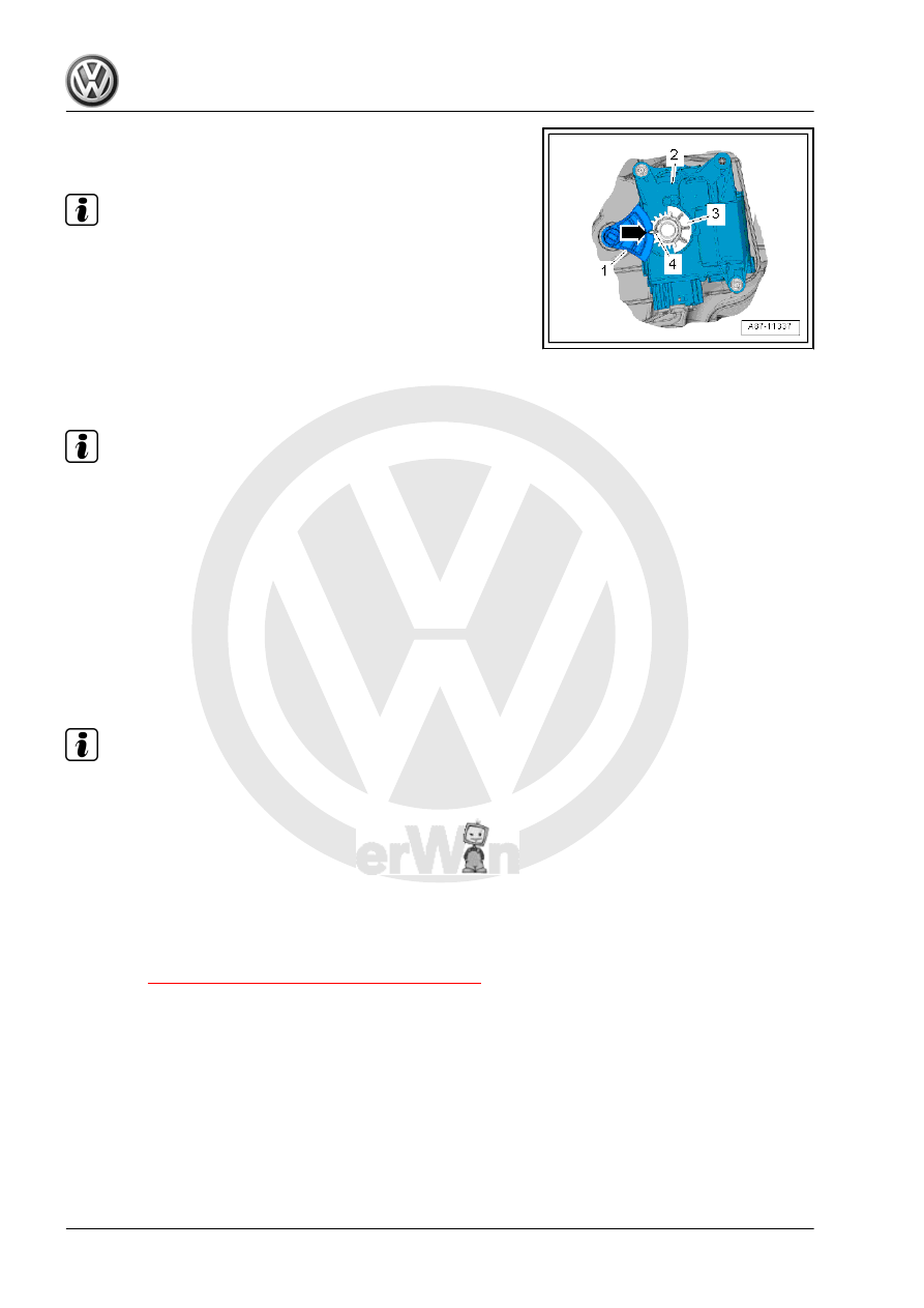
– Mount the actuator -2- onto the air distribution housing. When
doing this, the toothed gear -3- on the actuator must engage
into the toothed gear -1- on the temperature door lever.
• The long tooth -4- must engage into the recess -arrow- on the
operating lever.
Note
♦
If the toothed gear on the actuator and the toothed gear on the
temperature door lever do not face each other, turn the mount
in the actuator.
♦
If the bolts cannot be installed, the actuator does not sit com‐
pletely on the housing.
– Switch on the ignition, connect the affected actuator to the ve‐
hicle wiring harness and select the setting for the desired
actuator position on the display control head (for example, the
center position). Wait until the actuator reaches the desired
position and switch the ignition off.
– Install the wiring harness so that it cannot come in contact with
any moving parts (for example, the lever on the actuator).
Note
Turn the actuator so far until it has reached a favorable position
for installation. The direction of rotation can be reversed by
switching the positive and negative.
– Check the Diagnostic Trouble Code (DTC) memory and erase
any displayed entries, then perform the “basic setting”. Refer
to Vehicle Diagnostic Tester in the “Guided Fault Finding”
function.
– Check the heater and Air Conditioning (A/C) unit function.
Tightening Specifications
♦ Refer to
⇒ “4.1 Overview - Heater and A/C Unit”, page 72
7.7
Fresh Air/Recirculating Air/Back Pres‐
sure Door Motor - V425- with Fresh Air/
Recirculating Air/Back Pressure Door
Motor Position Sensor - G644- , Remov‐
ing and Installing
Special tools and workshop equipment required
♦ Vehicle Diagnostic Tester
Perform the following work first: