Volkswagen Golf / Golf GTI / Golf Variant. Manual - part 549
2
Refrigerant Circuit
⇒ “2.1 System Overview - Refrigerant Circuit”, page 32
⇒ “2.2 Overview - Condenser”, page 35
⇒ “2.3 Refrigerant Circuit Pressure Sensor G805 , Removing and
Installing”, page 36
⇒ “2.4 Expansion Valve, Removing and Installing”, page 37
⇒ “2.5 Condenser, Removing and Installing”, page 40
⇒ “2.6 Dryer Bag, Removing and Installing”, page 42
⇒ “2.7 Refrigerant Lines with Inner Heat Exchanger, Removing
and Installing”, page 52
⇒ “2.8 Low Pressure Side Refrigerant Line Balance Weight, Re‐
moving and Installing”, page 54
⇒ “2.9 Evacuating and Charging Valve, Removing and Installing,
Low and High Pressure Side”, page 55
2.1
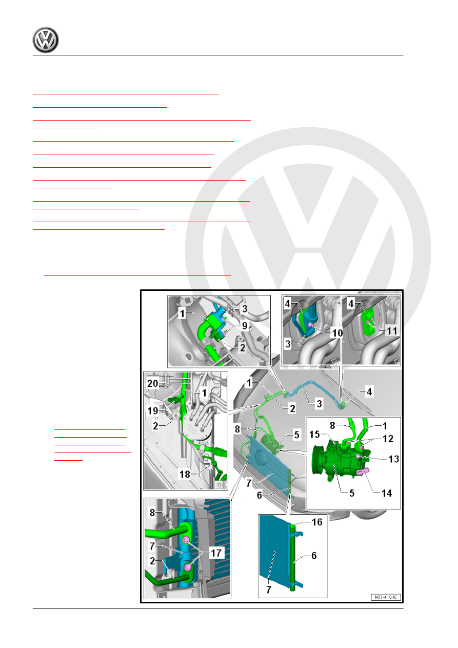
System Overview - Refrigerant Circuit
– When working on the refrigerant circuit, note the information.
Refer to
⇒ “4.1 Refrigerant Circuit, Specialized Repairs”, page 6
1 - Refrigerant Line - Low Pres‐
sure Side
❑ To the refrigerant line
with the inner heat ex‐
changer
❑ An additional balance
weight may be present
on this refrigerant line
depending on the refrig‐
erant line version and
the production period.
Refer to the Parts Cata‐
log.
❑ Balance weight remov‐
ing and installing. Refer
to
2 - Refrigerant Line - High
Pressure Side
❑ To the refrigerant line
with the inner heat ex‐
changer
3 - Refrigerant Line with Inner
Heat Exchanger
❑ In the inner heat ex‐
changer, the flowing flu‐
id warm refrigerant on
the high pressure side is
delivered into the low
pressure side as flow‐
ing, vapor, cold refriger‐
ant to increase the effi‐
ciency of the Air Condi‐