Volkswagen Golf / Golf GTI / Golf Variant. Manual - part 498
 

  Index      Volkswagen     Volkswagen Golf / Golf GTI / Golf Variant - service repair manual 2013 year


Search            copyright infringement  


Content   ..  496  497  498  499   ..


Volkswagen Golf / Golf GTI / Golf Variant. Manual - part 498


Caution

This procedure contains mandatory replaceable parts. Refer

to component overview prior to starting procedure.

Mandatory Replacement Parts
♦ Nut - Selector Lever to Shift Lever Shaft with Shift Lever Cover
♦ Lock Washer - Cable Retainer to Selector Lever
♦ Lock Washer - Cable Mounting Bracket to Cable Retainer
Removing
– Disconnect the battery ground cable. Refer to ⇒  Electrical

Equipment; Rep. Gr.  27 ; Battery; Battery, Disconnecting and

Connecting .

– Remove the boot with the shift lever knob and, if necessary,

remove the noise insulation from the center console frame as

well. Refer to

⇒ “1.4 Gearshift Knob, Removing and Installingg”, page 62

 .

The Footwell Rear Channel is Located Above the Nut for the

Center Console on Some Vehicles:
– Remove the center console. Refer to ⇒  Body Interior; Rep.

Gr.  68 ; Center Console; Overview - Center Console .

– Remove rear channel footwell. Refer to ⇒  Heating, Ventilation

and Air Conditioning; Rep. Gr.  87 ; Air Routing; Overview - Air

Routing and Air Distribution in Passenger Compartment .

– Remove the center console mounting bracket nuts. Refer to

⇒  Body Interior; Rep. Gr.  68 ; Center Console; Center Con‐

sole, Removing and Installing .

– Remove the nuts from the shift lever housing. Refer to

⇒ Fig. ““Installed Position of Gearshift Housing Nuts -arrow-

”“ , page 65

 .

– Lower the shift lever housing.
• If it is not possible to lower the shift lever housing, then the

nuts on the shift lever housing are located under the bracket

on the center console.

• Remove the center console mounting bracket. Refer to ⇒ 

Body Interior; Rep. Gr.  68 ; Center Console; Center Console,

Removing and Installing .

If the Center Console Bracket Cannot Be Removed Separately:
– Remove the center console. Refer to ⇒  Body Interior; Rep.

Gr.  68 ; Center Console; Center Console, Removing and In‐

stalling .

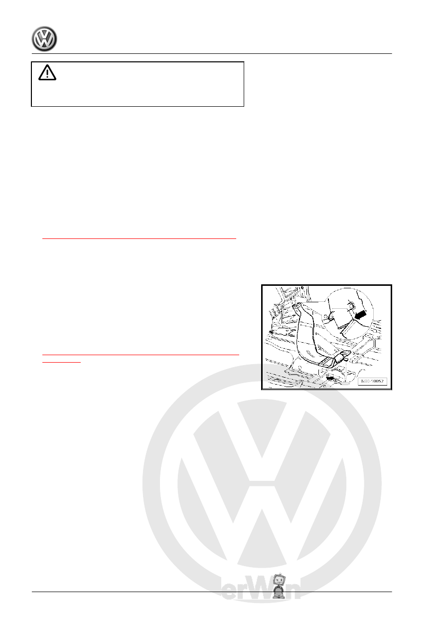
Installed Position of Gearshift Housing Nuts -arrow-
– Remove the shift lever housing nuts -arrows-.
– Remove center console and center console mounting bracket.

Refer to ⇒  Body Interior; Rep. Gr.  68 ; Center Console; Over‐

view - Center Console .

– Remove rear channel footwell. Refer to ⇒  Heating, Ventilation

and Air Conditioning; Rep. Gr.  87 ; Air Routing; Overview - Air

Routing and Air Distribution in Passenger Compartment .

Installed Position of Noise Insulation and Gearshift Housing Nuts

-arrows-.
– Remove noise insulation and shift lever housing nuts

-arrows-.

– Remove noise insulation from the shift lever housing. Refer to

⇒  Body Interior; Rep. Gr.  68 ; Center Console; Overview -

Center Console .

– Remove the entire air filter housing if it is located above the

shift lever mechanism.

Vehicles with a Turbo Diesel Engine
– Refer to ⇒  Engine Mechanical, Fuel Injection and Glow Plug;

Rep. Gr.  23 ; Air Filter; Air Filter Housing, Removing and In‐

stalling .

Vehicles with a Gasoline Engine
– Refer to ⇒  Engine Mechanical, Fuel Injection and Ignition;

Rep. Gr.  24 ; Air Filter; Air Filter Housing, Removing and In‐

stalling .

Continuation for All

Remove Shift Cable from Transmission Shift Lever
– Lift the clamp and remove the lock washer -1- for the shift cable

from the shift lever -2-.

– Remove the shift cable from the pin -arrow- from the shift lever

-2-.

Disconnecting the Cable Retainer from the Selector Cable
– Pull the securing mechanism all the way forward in direction

of -arrow 1- and then unlock to the left in direction of

-arrow 2-.

– Push the relay lever forward and guide the selector cable out

of the cable retainer.

Note

The cable retainer may be removed only when the relay lever is

removed. Refer to

⇒ Fig. ““With the Selector Relay Lever Removed: Pry the Selector

Cable Retainer Out of the Selector Relay Lever.”“ , page 67

 .

– Remove cable bracket from transmission, remove the nut -1-

and bolts -2-.

Caution

There is a danger of causing damage to the decoupling ele‐

ment on the exhaust pipe.

♦ Pay attention to ⇒  Engine Mechanical, Fuel Injection and

Ignition; Rep. Gr.  26 ; Emissions Control; Overview -

Emissions Control .

– Remove the exhaust pipe under the shift lever mechanism.

Refer to ⇒  Engine Mechanical, Fuel Injection and Ignition;

Rep. Gr.  26 ; Exhaust Pipes/Mufflers; Overview - Muffler .

– Remove the heat shield under the shift lever mechanism.
Removing the heat shield. Refer to ⇒  Body Exterior; Rep. Gr. 

66 ; Molding/Trim/Extensions/Trim Panels; Floor Heat Shield,

Removing and Installing .
– Pivot shift housing downward and remove with cables.

Relay Lever with Cable Retainer, Removing and Installing
Removing
– Remove the clip -arrow 1- and then remove the relay lever

together with the cable retainer -arrow 2-.

Installing

Note

Lubricate the bearing areas and the sliding surfaces. Grease al‐

location. Refer to the Parts Catalog.

– Install the relay lever and cable retainer -arrow 2- all the way

into the gearshift cover.

– Install the clip -arrow 1- and make sure it is locked into place.

With the Selector Relay Lever Removed: Pry the Selector Cable

Retainer Out of the Selector Relay Lever.
• The relay lever is removed.
– Insert a screwdriver -A- between the bushing -B- and the relay

lever.

Installing the Selector Cable Retainer on the Relay Lever
• The relay lever is removed.
• Lubricate cable retainer locating bore
• Grease allocation. Refer to the Parts Catalog.
• The cable retainer may only be installed at the bushing in the

direction of -arrow-.

• The cable retainer must move freely on the relay lever.
• The cable retainer must be behind the tab.
• Make sure it engages securely.

Removing the Cable Retainer from the Shift Lever Cable and Se‐

lector Cable
– Pull the safety mechanism all the way forward in the direction

of -arrow 1- and lock it in direction of -arrow 2-.

– Remove the cable -B- from the cable retainer -A-.
Shift Mechanism, Installing
Install in reverse order of removal. Note the following:


Content   ..  496  497  498  499   ..