Volkswagen Golf / Golf GTI / Golf Variant. Manual - part 469


  Index      Volkswagen     Volkswagen Golf / Golf GTI / Golf Variant - service repair manual 2013 year


Search            copyright infringement  


Content   ..  467  468  469  470   ..


Volkswagen Golf / Golf GTI / Golf Variant. Manual - part 469


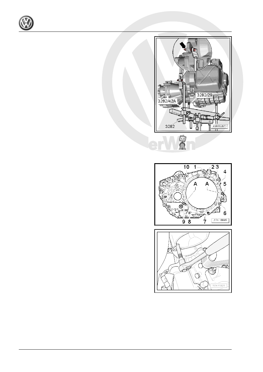
– Place the transmission with the Transmission Support - 3282-

on the Engine and Gearbox Jack - VAS 6931- .

– Place the Engine and Gearbox Jack - VAS6931- under the

vehicle. The arrow symbol on the Transmission Support -

Mounting Plate 42A - 3282/42A- points in the direction of travel

of the vehicle.

– Tilt the transmission to the left by adjusting the spindles on the

Transmission Support - 3282- . The lift the transmission.

Pay attention to the selector lever cable when lifting the trans‐

mission. Guide the cable into the cable bracket as early as

possible.
The cable is not lubricated.
– Align the transmission to the engine and position on the cyl‐

inder block.

Guide the engine and transmission together by hand until the en‐

tire surface of both flanges come into contact with one another.
– Adjust the transmission mount until the engine and transmis‐

sion “are aligned”.

– Turn the crankshaft slightly if necessary.
Be careful not to get any lines caught when installing the trans‐

mission.

– Tighten the bolts -5 through 9- to the tightening specification.
– After transmission was bolted to engine at bottom, remove the

Transmission Support - 3282- from transmission.

– Tighten the upper engine/transmission bolts -1, 3 and 10- to

the tightening specification using the Insert Tool - 18mm -

T10179- .

The bolt -3- is located in the starter hole. Use the Socket - Xzn 14

- T10061- for this bolt.
– Align the engine/transmission assembly free of tension. Refer

to ⇒  Engine Mechanical, Fuel Injection and Ignition; Rep. Gr. 

10 ; Subframe Mount; Subframe Mount, Adjusting .

Install the left subframe mount as follows:
– Replace all the bolts -1 and 2-.
– Install the new bolt first hand-tight.
– Install the bolts -1- in the transmission bracket -A-.
– The align the engine/transmission in its installation position.

Lift until the transmission bracket is touching the transmission

mount completely.

Caution

There is a risk of damaging the threads in transmission bracket

by inserting the bolts at an angle.

♦ Before installing the bolts -2-, the transmission bracket

and transmission mount support arm must be absolutely

parallel to each other. If necessary, lift the back of the

transmission using the Engine and Gearbox Jack .

– Pry the transmission bracket -A- into the seat using a screw‐

driver while tightening the bolts -2-.

WARNING

Remove the Engine Support Bridge - 10-222A- only when the

bolts for the left and right subframe mount have been tightened

to the specification.

– Remove the Engine Support Bridge - 10-222A- .
– Install the starter. Refer to ⇒  Electrical Equipment; Rep. Gr. 

27 ; Starter; Starter, Removing and Installing .

Connect the connector -A- on the DSG Transmission Mechatronic

- J743- as follows:
– The arrow -D- on the DSG Transmission Mechatronic - J743-

-B- must line up with the connector -A- as well as with the tab

-C-.

– Connect the connector -A- carefully all the way and then turn

the lock “clockwise” in direction of -arrow-.

– Attach the drive axles to the transmission. Refer to ⇒  Sus‐

pension, Wheels, Steering; Rep. Gr.  40 ; Drive Axle; Drive

Axle, Removing and Installing .

– Install the heat shield over the right drive axle, if equipped.

Refer to ⇒  Suspension, Wheels, Steering; Rep. Gr.  40 ; Drive

Axle; Drive Axle, Removing and Installing .

– Install the subframe. Refer to ⇒  Suspension, Wheels, Steer‐

ing; Rep. Gr.  40 ; Subframe; Subframe with Steering Gear,

Removing and Installing .

– Attach the pendulum support to the transmission by tightening

the bolts -11-. Refer to ⇒  Rep. Gr.  10 ; Subframe Mount;

Overview - Subframe Mount .

– Selector lever cable lock washers -arrows- must be replaced.
– Adjust the selector lever cable. Refer to

⇒ “2.8 Selector Lever Cable, Checking and Adjusting”,

page 68

 .

– Install the charge air pipe. Refer to ⇒  Engine Mechanical, Fuel

Injection and Ignition; Rep. Gr.  21 ; Charge Air System; Over‐

view - Charge Air System .

– Install the coolant hoses on the transmission fluid cooler.
– Attach the cable bracket to the transmission cover.
– Install the battery tray and the battery. Refer to ⇒  Electrical

Equipment; Rep. Gr.  27 ; Battery; Battery, Disconnecting and

Connecting .

– Install the air filter housing:
♦ Gasoline engine. Refer to ⇒  Rep. Gr.  24 ; Air Filter; Air Filter

Housing, Removing and Installing .

♦ Diesel engine. Refer to ⇒  Rep. Gr.  23 ; Air Filter; Air Filter

Housing, Removing and Installing .

– Install the engine cover. Refer to ⇒  Rep. Gr.  10 ; Engine

Cover; Engine Cover, Removing and Installing .

– Check the coolant level and fill if necessary. Refer to ⇒  Engine

Mechanical, Fuel Injection and Ignition; Rep. Gr.  19 ; Cooling

System/Coolant; Coolant, Draining and Filling .

– Check the fluid level and fill if necessary. Refer to

⇒ “9.1 Transmission Fluid Level, Checking”, page 113

 .

– Install the lower section of the left front wheel housing liner.

Refer to ⇒  Body Exterior; Rep. Gr.  66 ; Wheel Housing Liner;

Overview - Front Wheel Housing Liner .

– Install the noise insulation. Refer to ⇒  Body Exterior; Rep. Gr. 

66 ; Noise Insulation; Overview - Noise Insulation .

– Attach the front wheels. Refer to ⇒  Suspension, Wheels,

Steering; Rep. Gr.  44 ; Wheels, Tires; Wheel Bolts, Tightening

Specifications .

Tightening Specifications
♦ Transmission to engine. Refer to

⇒ “3.3 Transmission Tightening Specifications”, page 96

 .

♦ Transmission bracket to transmission. Refer to

⇒ “4 Subframe Mount”, page 97

 .

♦ Cable bracket on the transmission cover. Refer to

⇒ “3.3 Transmission Tightening Specifications”, page 96

 .

♦ Subframe mount to transmission bracket. Refer to

⇒ “4.1 Overview - Subframe Mount”, page 97

 .


Content   ..  467  468  469  470   ..