Volkswagen Golf / Golf GTI / Golf Variant. Manual - part 467


  Index      Volkswagen     Volkswagen Golf / Golf GTI / Golf Variant - service repair manual 2013 year


Search            copyright infringement  


Content   ..  465  466  467  468   ..


Volkswagen Golf / Golf GTI / Golf Variant. Manual - part 467


– Remove the starter -A-. Refer to ⇒  Electrical Equipment; Rep.

Gr.  27 ; Starter; Starter, Removing and Installing .

Remove the »lower« bolt first.

Caution

There is a risk of damaging the DSG Transmission Mecha‐

tronic - J743- with static electricity.

♦ Do not touch contacts in DSG Transmission Mechatronic

- J743- connector with hands.

– To discharge any static electricity, touch the vehicle ground

with hand (without wearing a glove). Refer to 

⇒ page 7

 .

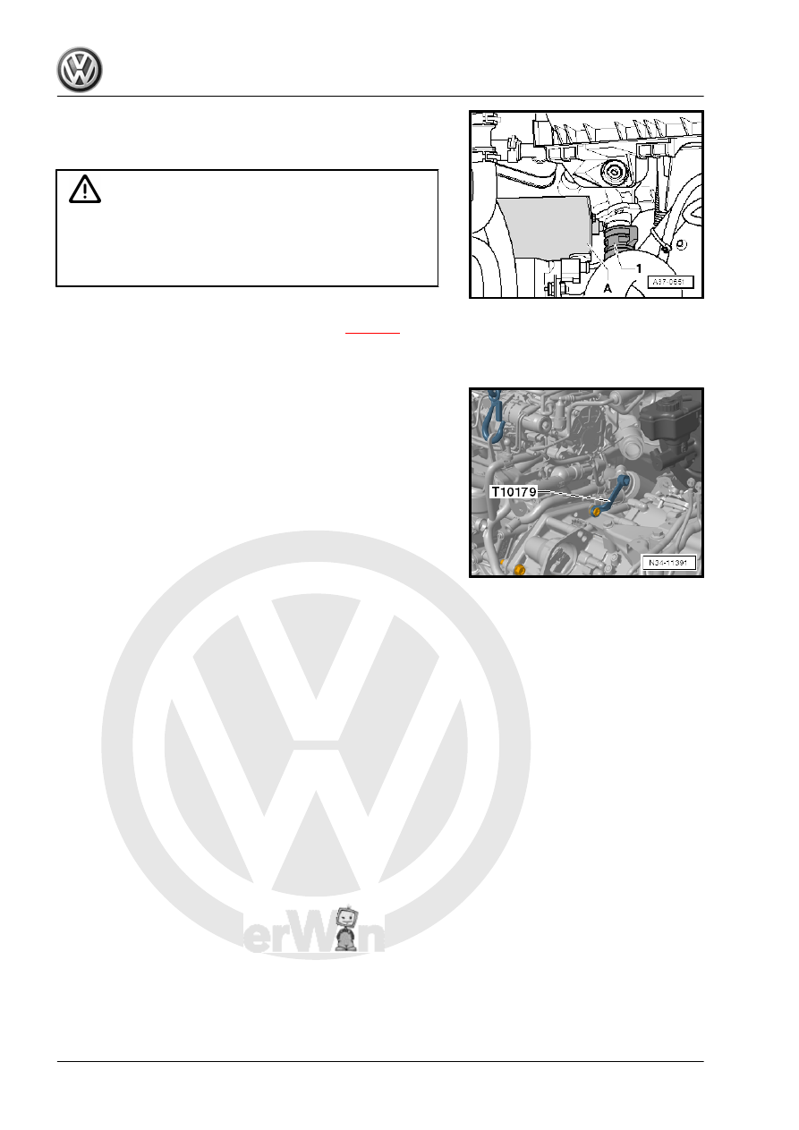
– Release the Mechatronic connector twist lock -1- by turning it

»counter-clockwise« and remove the connector.

– Remove all upper engine/transmission connecting bolts.

These tools are suitable for this.

One bolt is located inside the hole for the starter -arrow-. Use

Socket - Xzn 14 - T10061- to remove the bolt.
– Remove windshield wiper arms. Refer to ⇒  Electrical Equip‐

ment; Rep. Gr.  92 ; Windshield Wiper System; Windshield

Wiper Arms, Removing and Installing .

– Remove the plenum chamber cover. Refer to ⇒  Body Exterior;

Rep. Gr.  50 ; Bulkhead; Plenum Chamber Cover, Removing

and Installing .

– If there are hose and cable connections located near the en‐

gine lifting eyes for the Engine Support Bridge - 10-222A- ,

these must now be removed.

– Attach the Engine Support Bridge - 10-222A- as follows:
The following are needed:
♦ Engine Support Bridge - Engine Support 31 - Adapter 1 -

10-222A/31-1-

♦ Engine Support Bridge - Engine Support 31 - Adapter 2 -

10-222A/31-2-

♦ Engine Support - Basic Set - Square Pipe - T40091/1-
♦ Engine Support - Basic Set Movable Joint - T40091/3-
♦ Engine Support - Supplement Kit Spindle - T40093/3-
♦ Engine Support Brackets - T40093/3-6-
♦ Engine/Gearbox Support Shackle (2 pc.) - 10-222A/12-
– Remove the caps over the suspension strut threaded connec‐

tions.

– Place the Engine Support Bridge - Engine Support 31 Adapter

1 - 10-222A/31-1- and Engine Support Bridge - Engine Sup‐

port 31 Adapter 2 - 10-222A/31-2- on the suspension strut

mounts.

The tabs -arrow- face the engine compartment.

– Slide the Engine Support - Supplement Kit Adapter 3 -

T40091/3- onto the Engine Support Bridge - 10-222A- .

– Fasten the Engine Support Bridge - 10-222A- on the Engine

Support Bridge - Engine Support 31 Adapter 1 - 10-222A/31-1-

and on the Engine Support Bridge - Engine Support 31 Adapt‐

er 2 - 10-222A/31-2- .

-A- = Engine Support Brackets - T40093/3-6- (⇒ next illustration)

– Remove fuel filter and set off to the side. Do not open the line

system. Refer to ⇒  Rep. Gr.  20 ; Overview - Fuel Filter .

– If present, remove wires from the front area of the tab on the

longitudinal member -arrow-. Do not disconnect line system.

– Position the Engine Support Brackets - T40093/3-6- on the

right longitudinal member.

– If necessary, carefully unclip the A/C system pipe in the front

area. Do not disconnect the line system. Refer to ⇒  Heating,

Ventilation and Air Conditioning; Rep. Gr.  87 ; System Over‐

view - Refrigerant Circuit .

• The Engine Support Brackets - T40093/3-6- locks with the pins

-A- behind the tab on the longitudinal member -arrow-.

– Install the Engine Support - Supplement Kit Spindle -

T40093/3- .

– Connect the Engine Support - Supplement Kit Spindle -

T40093/3- over the Engine Support - Basic Set Square Pipe -

T40091/1- with the Engine Support Bridge - 10-222A- and

tension it (⇒ previous illustration).

• The Engine Support - Basic Set Square Pipe - T40091/1- must

be flush with the Engine Support - Basic Set Movable Joint -

T40091/3- and the Engine Support - Supplement Kit Spindle

- T40093/3- (⇒ previous illustration).

– Then engage the Spindles in the lifting eyes, as shown.
– Pretension the engine/transmission assembly and Engine

Support Bridge - 10-222A- via the Spindles .

– Loosen left and right front wheel bolts.
– Lift the vehicle, all four mounts from lifting platform at the same

height.

– Remove the front wheels.
– Remove the noise insulation. Refer to ⇒  Body Exterior; Rep.

Gr.  66 ; Noise Insulation; Overview - Noise Insulation .

– Remove the lower section of the left front wheel housing liner.

Refer to ⇒  Body Exterior; Rep. Gr.  66 ; Wheel Housing Liner;

Overview - Front Wheel Housing Liner .

– Remove the wires and bracket from the front of the transmis‐

sion cover -arrows- (two M6 nuts).

– Route the wires near the transmission cover upward and tie

them up.


Content   ..  465  466  467  468   ..