Volkswagen Golf / Golf GTI / Golf Variant. Manual - part 459


  Index      Volkswagen     Volkswagen Golf / Golf GTI / Golf Variant - service repair manual 2013 year


Search            copyright infringement  


Content   ..  457  458  459  460   ..


Volkswagen Golf / Golf GTI / Golf Variant. Manual - part 459


Caution

This procedure contains mandatory replaceable parts. Refer

to component overview prior to starting procedure.

Mandatory Replacement Parts
♦ Clamp - Shift Handle
Short Description:
The handle is removed together with the shift cover.
Removing
– Move the selector lever into “D”.
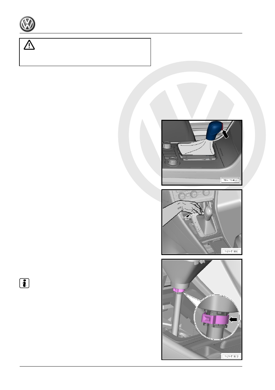
It is not necessary to pull out the button -arrow- manually. The

push button locks in the installation position by itself when the

handle is removed.
– Open the storage compartment door.
– Grab and under the shift cover by hand and pulling upward

unclip the cover.

– Disconnect the connector.

– Cut the clamp under the boot -arrow- with a side cutter.
– Pull the handle up without pressing the button.

Note

Do not push the button once the handle has been removed oth‐

erwise it will not be possible to remove the handle again.

Installing
Install in reverse order of removal. Note the following:
• The selector lever is in the “D” position.

Note

There is the possibility that the button can be pressed into the

handle. Never install the handle when the button is pressed in.

Move the button in the installation position. Refer to

⇒ “2.4 Button in Handle, Moving Into Installation Position”,

page 53

 .

A new handle is delivered with an assembly fastener. Pull out

the safety catch in direction of -arrow- just before installing the

new handle.

– Install the handle with a new clamp -arrow-. Do not clamp the

clamp yet.

– Press the button after installing it.

Note

If the button stays in the handle after being pressed, this means

it was installed incorrectly. If this happens, remove the handle

again and move the button in the installation position again. Refer

to

⇒ “2.4 Button in Handle, Moving Into Installation Position”,

page 53

 . Install the handle again.

– If the button after being pressed return to its starting position,

the clamp can be clamp off using Hose Clamp Pliers -

VAG1275A- .

– Connect the connector.
– Clip on the cover.

2.4

Button in Handle, Moving Into Installa‐

tion Position

If the button was pushed in by mistake, the installed position can

be set again.

There are two ways to move the button into the installation posi‐

tion, “with” or “without” assembly fastener. The following de‐

scribes both ways.
Moving the Handle “with” an Assembly Fastener into the Instal‐

lation Position:
Make sure the assembly fastener has an eye -arrow- at the front.

Other assembly fasteners cannot be used.

– Press the button and push the assembly fastener (with the

eye) -arrow- all the way in until it latches into place. Then re‐

lease the button. The button locks into the installation position

when the assembly fastener is pulled out.

Moving the Handle “without” an Assembly Fastener into the In‐

stallation Position:

– Remove the trim -A- from the handle.

– Push the small lever -1- into the groove -2- with a screwdriver.

This pushes the button -3- into the installation position.
-I- the button is in the pressed position
-II- the button is in the installation position

Note

Push the lever into the groove and no further.

Install the trim back onto the selector mechanism only after the

handle is installed. This way it is possible to see if the small

lever fits into the pull rod when the button is pushed.

2.5

Selector Mechanism, Removing and In‐

stalling

⇒ “2.5.1 Shift Mechanism with Selector Lever Cable, Removing

and Installing”, page 55
⇒ “2.5.2 Gearshift Mechanism without Selector Lever Cable, Re‐

moving and Installing, ZF”, page 57
⇒ “2.5.3 Shift Lever Mechanism without Selector Lever Cable,

Removing and Installing, ECS”, page 60

2.5.1

Shift Mechanism with Selector Lever

Cable, Removing and Installing

Short Description
Remove the center console inside the passenger compartment.
It is necessary to remove the heat shield under the vehicle.
Removing
– Remove the selector lever handle. Refer to

⇒ “2.3 Selector Lever Handle, Removing and Installing”, page

51

 .

– Remove the center console. Refer to ⇒  Body Interior; Rep.

Gr.  68 ; Center Console; Center Console, Removing and In‐

stalling .

– Remove the air guide channel from the center console. Refer

to ⇒  Heating, Ventilation and Air Conditioning; Rep. Gr.  87 ;

Air Routing; Overview - Air Routing and Air Distribution in Pas‐

senger Compartment .

– Remove left and right bolts -1- and bracket -2-.
– Disconnect the connector from the selector mechanism to the

vehicle wiring harness.

– Remove the air filter housing:
♦ Gasoline engine. Refer to ⇒  Engine Mechanical, Fuel Injec‐

tion and Ignition; Rep. Gr.  24 ; Air Filter; Air Filter Housing,

Removing and Installing .

♦ Diesel engine. Refer to ⇒  Rep. Gr.  23 ; Air Filter; Air Filter

Housing, Removing and Installing .


Content   ..  457  458  459  460   ..