Volkswagen Golf / Golf GTI / Golf Variant. Manual - part 460


  Index      Volkswagen     Volkswagen Golf / Golf GTI / Golf Variant - service repair manual 2013 year


Search            copyright infringement  


Content   ..  458  459  460  461   ..


Volkswagen Golf / Golf GTI / Golf Variant. Manual - part 460


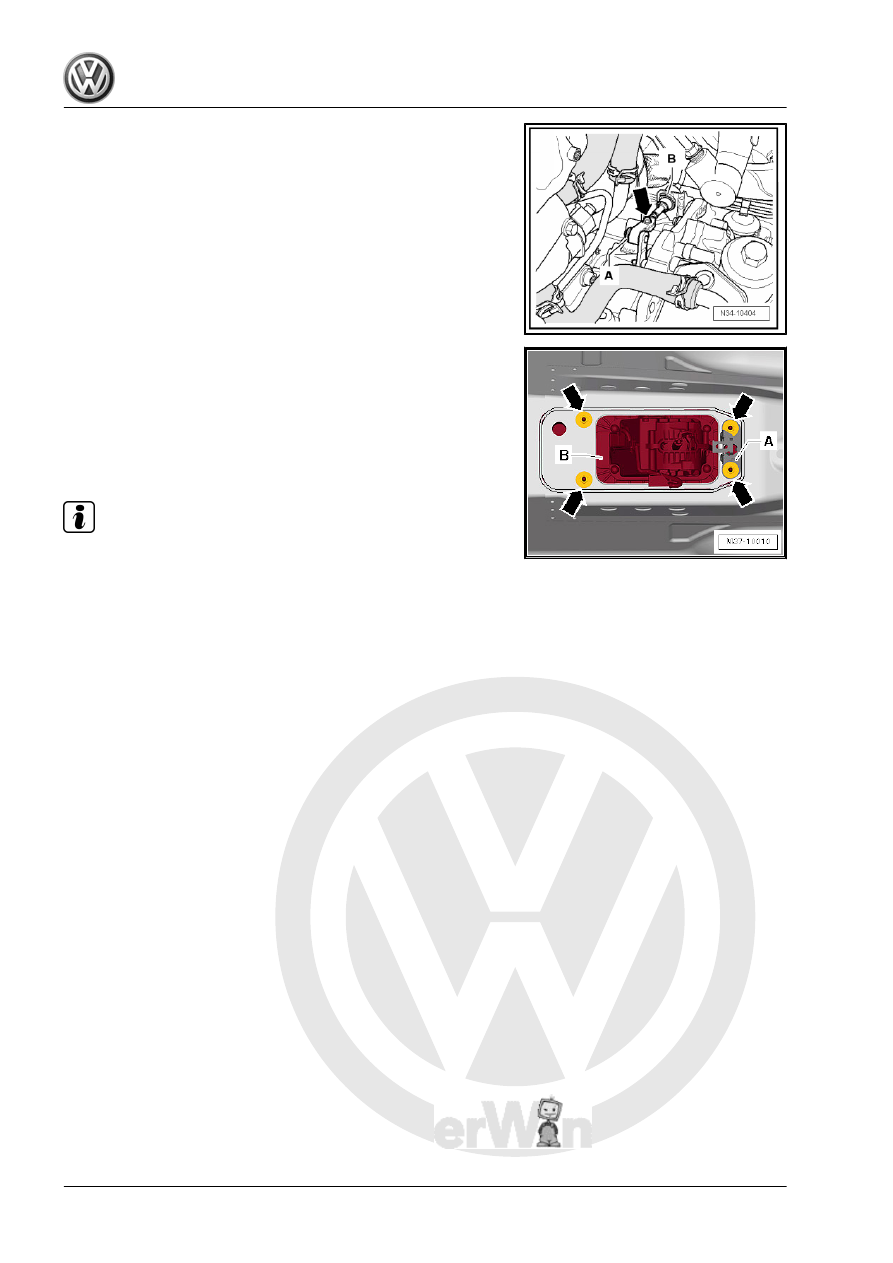
Loosen the adjusting screw -arrow-.
– Remove the lock washers -A and B-. The lock washers must

later be replaced when adjusting selector lever cable.

Use pliers to remove the lock washer -B-. Do not use a sharp-

edged lever. Otherwise the selector lever cable could get dam‐

aged.
– Remove the center tunnel heat shield under the gearshift

mechanism. Refer to ⇒  Body Exterior; Rep. Gr.  66 ; Molding/

Trim/Extensions/Trim Panels; Floor Heat Shield, Removing

and Installing .

– Remove the bracket -A-, if equipped.
– Remove the nuts -arrows- in the vehicle interior.
– Remove the selector mechanism -B- with the selector lever

cable and selector housing downward.

Installing
Install in reverse order of removal. Note the following:

Note

Do not bend or kink the selector lever cable.

Do not lubricate the selector lever cable.

After installation, the selector lever cable movement must be

checked and adjusted.

– Install the heat shield under the gearshift mechanism. Refer

to ⇒  Body Exterior; Rep. Gr.  66 ; Molding/Trim/Extensions/

Trim Panels; Floor Heat Shield, Removing and Installing .

– Install the bracket -2-. Refer to ⇒  Body Interior; Rep. Gr.  68 ;

Center Console; Center Console, Removing and Installing .

– Install the air guide channel from the center console. Refer to

⇒  Heating, Ventilation and Air Conditioning; Rep. Gr.  87 ; Air

Routing; Overview - Air Routing and Air Distribution in Pas‐

senger Compartment .

– Install the center console. Refer to ⇒  Body Interior; Rep. Gr. 

68 ; Center Console; Center Console, Removing and Instal‐

ling .

– Install the selector lever handle. Refer to

⇒ “2.3 Selector Lever Handle, Removing and Installing”, page

51

 .

– Adjust the selector lever cable. Refer to

⇒ “2.8 Selector Lever Cable, Checking and Adjusting”,

page 68

 .

– Check the selector mechanism. Refer to

⇒ “2.7 Gearshift Mechanism, Checking”, page 67

 .

– Install the air filter housing:
♦ Gasoline engine. Refer to ⇒  Engine Mechanical, Fuel Injec‐

tion and Ignition; Rep. Gr.  24 ; Air Filter; Air Filter Housing,

Removing and Installing .

♦ Diesel engine. Refer to ⇒  Rep. Gr.  23 ; Air Filter; Air Filter

Housing, Removing and Installing .

Tightening Specifications
♦ Selector mechanism to the body. Refer to

⇒ “2.1 Overview - Selector Mechanism”, page 47

 .

2.5.2

Gearshift Mechanism without Selector

Lever Cable, Removing and Installing,

ZF

Caution

This procedure contains mandatory replaceable parts. Refer

to component overview prior to starting procedure.

Mandatory Replacement Parts
♦ Lock Washer - Locking Mechanism
Short Description
Remove the center console inside the passenger compartment.
It is necessary to remove the heat shield under the vehicle.
Removing
– Remove the selector lever handle. Refer to

⇒ “2.3 Selector Lever Handle, Removing and Installing”, page

51

 .

– Remove the center console. Refer to ⇒  Body Interior; Rep.

Gr.  68 ; Center Console; Center Console, Removing and In‐

stalling .

– Remove the air guide channel from the center console. Refer

to ⇒  Heating, Ventilation and Air Conditioning; Rep. Gr.  87 ;

Air Routing; Overview - Air Routing and Air Distribution in Pas‐

senger Compartment .

– Remove the bracket -2-, to do this remove the left and right

bolts -1-.

– Disconnect the connector from the selector mechanism to the

vehicle wiring harness.

– Position the selector lever on the selector mechanism in the

“N” position. The cable can only be loosened in this position.

– Remove the center tunnel heat shield under the gearshift

mechanism. Refer to ⇒  Body Exterior; Rep. Gr.  66 ; Molding/

Trim/Extensions/Trim Panels; Floor Heat Shield, Removing

and Installing .

– Remove the plugs, and remove the lock washer -arrow-.
Always replace the lock washer.

– Insert a large screwdriver into the grooves on the locking

mechanism and turn 90° in the direction of the -arrow-.

– Remove the cable from the selector mechanism.

– Remove the bracket -A-, if equipped.
– Remove the nuts -arrows- in the vehicle interior.
– Remove the selector mechanism -B- with the gearshift hous‐

ing downward.

Installing
Install in reverse order of removal. Note the following:

Note

Do not bend or kink the selector lever cable.

Do not lubricate the selector lever cable.

After installation, the selector lever cable movement must be

checked and adjusted.

• The selector lever for the gearshift mechanism is in the “N”

position. The cable can only be locked in this position.

– Guide the cable into the selector mechanism in direction of

-arrow- until the locking mechanism -arrow- is visible.

– Turn the locking mechanism 90° in the direction of the

-arrow- with a large screwdriver.

– The cable is correctly locked when the grooves on the locking

mechanism are at a right angle to the cable.

– Install new lock washer -arrow- and replace the plugs.
– Install the heat shield under the shift lever mechanism. Refer

to ⇒  Body Exterior; Rep. Gr.  66 ; Molding/Trim/Extensions/

Trim Panels; Floor Heat Shield, Removing and Installing .


Content   ..  458  459  460  461   ..