Volkswagen Golf / Golf GTI / Golf Variant. Manual - part 453
34 – Controls, Housing
1
Mechatronic
⇒ “1.1 Overview - Mechatronic”, page 28
⇒ “1.2 Mechatronic, Removing and Installing”, page 30
1.1
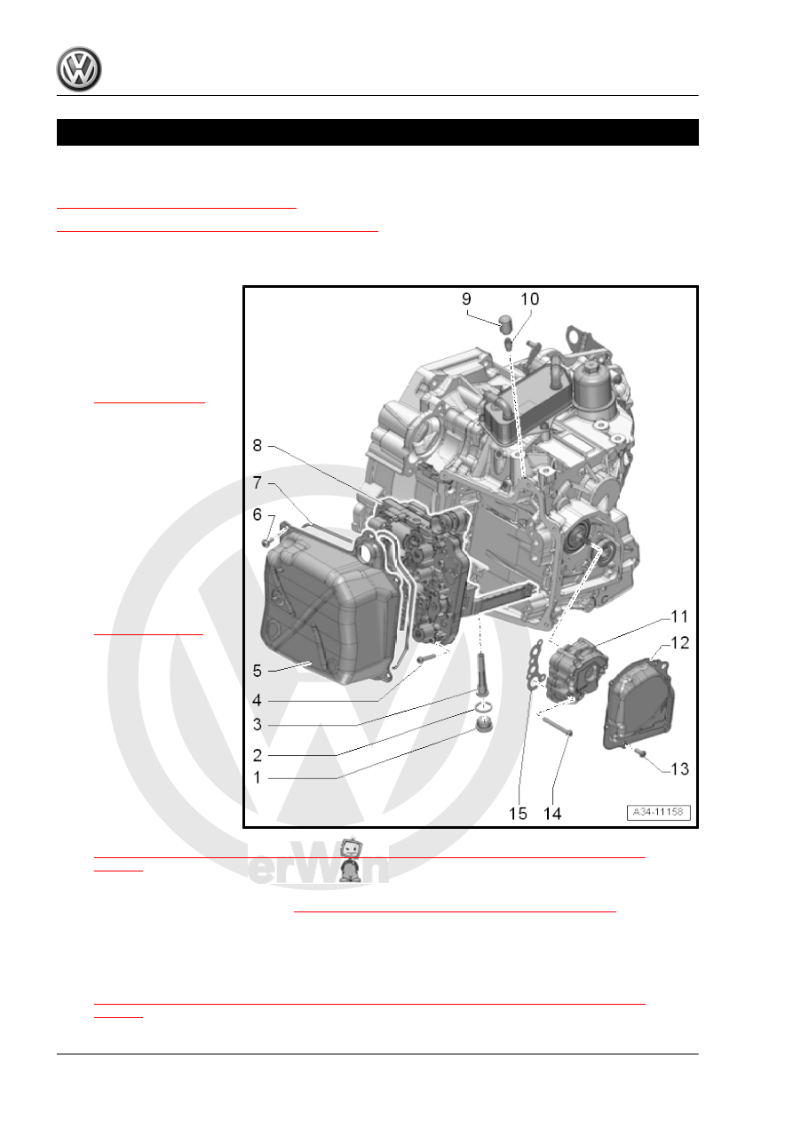
Overview - Mechatronic
1 - Transmission Fluid Drain
and Check Plug
❑ 45 Nm
❑ There is an overflow
pipe with a 8 mm inner
hex behind this bolt
-item 3-
❑ Drain the transmission
fluid via the drain- and
check plug and re‐
moved overflow pipe
2 - Seal
❑ Replace after removing
3 - Overflow Pipe
❑ 3 Nm
❑ Plastic
❑ To drain the transmis‐
sion fluid, remove the
drain and check plugs.
Refer to -item 1-
remove the overflow
pipe.
❑ The length of the over‐
flow pipe determines the
fluid level inside the
transmission
❑ Allocate according to
the Parts Catalog.
4 - Bolt
❑ Replace after removing
❑ Quantity: 10
❑ Tightening specification
and sequence. Refer to
⇒ Fig. ““Tightening Specification and Sequence for DSG Transmission Mechatronic -J743- ”“ ,
5 - Transmission Cover
❑ Removing and installing. Refer to
⇒ “1.2 Mechatronic, Removing and Installing”, page 30
6 - Bolt
❑ Replace after removing
❑ Quantity: 5
❑ Tightening specification and sequence. Refer to
⇒ Fig. ““Tightening Specification and Sequence for DSG Transmission Mechatronic -J743- ”“ ,