Volkswagen Golf / Golf GTI / Golf Variant. Manual - part 451


  Index      Volkswagen     Volkswagen Golf / Golf GTI / Golf Variant - service repair manual 2013 year


Search            copyright infringement  


Content   ..  449  450  451  452   ..


Volkswagen Golf / Golf GTI / Golf Variant. Manual - part 451


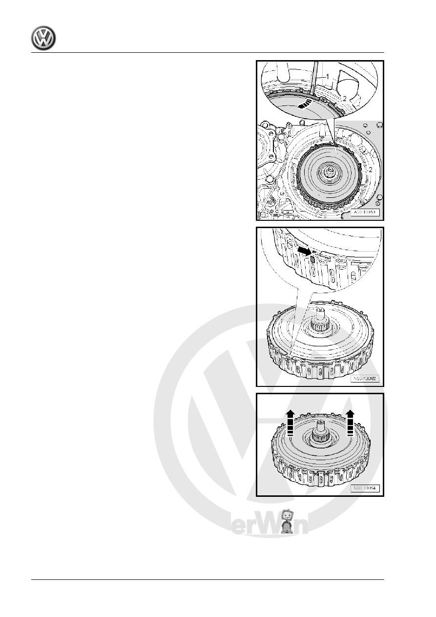
– Remove the circlip -2- from the drive plate with a screwdriver

-1- in direction of -arrow- and dispose of it.

Important! Installed Position of the Drive Plate
– Verify that the protruding tab -arrow- of the drive plate is posi‐

tioned between the color-marked teeth of the outer clutch pack

carrier.

If no marking is available:
– Mark the location of the tab to the outer clutch pack carrier

circumference with a waterproof marker as shown in the illus‐

tration.

• When installing, the drive plate tab must be placed back on

this marked location.

– Remove the drive plate in the direction of -arrows-.

– Remove the circlip -arrow- and dispose of it.

Note

This circlip must be replaced and re-measured during installation.

Caution

Carefully remove the DSG

®

 clutch. Make sure that no other

parts of the clutch fall out; for this reason, never turn over the

clutch!

– Remove the DSG

®

 clutch.

– Remove the pump shaft -A-.
– The pump shaft is inserted after installing the new dual clutch.

Lay the shaft down until then.

– Install the dual clutch. Refer to

⇒ “1.4 DSG® Clutch, Installing”, page 21

 .

1.4

DSG

®

 Clutch, Installing

Special tools and workshop equipment required
♦ Clutch Retaining Bar - T10303-
♦ Dial Gauge Holder - VW387-
♦ Dial Gauge - 0-10mm - VAS6079-

Caution

This procedure contains mandatory replaceable parts. Refer

to component overview prior to starting procedure.

Mandatory Replacement Parts
♦ Circlip - DSG

®

 Clutch and Circlip

♦ Circlip

Caution

♦ The drive plate of a new clutch is not secured with the

circlip, it only sits “taut” in the clutch.

♦ Thus, press the drive plate into the outer clutch pack car‐

rier with both thumbs during the following steps.

♦ The drive plate must be engaged between the teeth of the

exterior clutch pack.

♦ If the drive plate is loosened, the clutch discs in the

DSG

®

 clutch can slip out of place and the DSG

®

 clutch

may not be correctly set during installation under certain

circumstances.

Installing

Caution

A »used« clutch must not be installed again.

– Take the DSG

®

 clutch out of the packaging by pressing the

drive plate into the outer clutch pack carrier with both thumbs.

– Check the bottom side of the multi-plate clutch to see if the 4

hub sealing rings are seated correctly and engage them in one

another if necessary.

• The ends of the rings should not stand over one another.
– Turn the rings one time. They must move freely and must not

stick.

Important! Installed Position of the Drive Plate
– Verify that the protruding tab -arrow- of the drive plate is posi‐

tioned between the color-marked teeth of the outer clutch pack

carrier.

If no marking is available:
– Mark the location of the tab to the outer clutch pack carrier

circumference with a waterproof marker as shown in the illus‐

tration.

• When installing, the drive plate tab must be placed back on

this marked location.

– Insert the Clutch Retaining Bar - T10303- in the positions on

the clutch cover as shown in the illustration.

– Set the DSG

®

 clutch using rotating and hub movements into

the clutch housing, but do not let it fall in. Press the drive plate

into the outer clutch pack carrier with both thumbs in the di‐

rection of -arrows- to install.

• A second technician should hold the Clutch Retaining Bar -

T10303- .

Note

The bolt remains installed until clutch end plate is installed.

♦ The DSG

®

 clutch must not be turned any more now, otherwise

the Clutch Retaining Bar - T10303- could be twisted in its po‐

sition.


Content   ..  449  450  451  452   ..