Volkswagen Golf / Golf GTI / Golf Variant. Manual - part 418


  Index      Volkswagen     Volkswagen Golf / Golf GTI / Golf Variant - service repair manual 2013 year


Search            copyright infringement  


Content   ..  416  417  418  419   ..


Volkswagen Golf / Golf GTI / Golf Variant. Manual - part 418


2.2.2

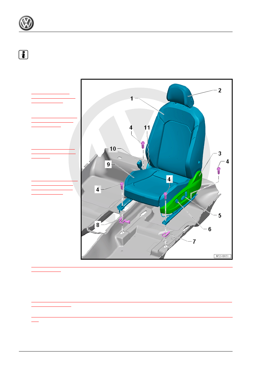
Overview - Front Seat, Power Seat

Note

The illustration shows the driver side front seat. The front seat on the front passenger side is similar.

1 - Backrest

❑ Overview. Refer to

⇒ “2.4.2 Overview -

Front Backrest, Power

Seat”, page 325

 .

❑ Removing and instal‐

ling. Refer to

⇒ “2.16 Front Backrest,

Removing and Instal‐

ling”, page 349

 .

2 - Headrest

❑ Removing and instal‐

ling. Refer to

⇒ “2.23 Headrest, Re‐

moving and Installing”,

page 360

 .

3 - Sill-Side Seat Trim Panel

❑ Removing and instal‐

ling. Refer to

⇒ “2.14.2 Door Sill Side

Seat Trim, Removing

and Installing, Power

Seat”, page 347

 .

4 - Screw

❑ 40 Nm
❑ Quantity: 4

5 - Seat Adjustment Control

Head

❑ Driver Seat Adjustment

Control Head - E470-

❑ Front Passenger Seat

Adjustment Control

Head - E471-

❑ Removing and instal‐

ling. Refer to

⇒ “2.38 Driver and Front Passenger Seat Adjustment Control Head E470 / E471 , Removing and Instal‐

ling”, page 373

 .

6 - Lumbar Support Adjustment Switch

❑ Driver Seat Lumbar Support Adjustment Switch - E176-
❑ Front Passenger Seat Lumbar Support Adjustment Switch - E177-
❑ Removing and installing. Refer to

⇒ “2.36 Driver/Front Passenger Seat Lumbar Support Adjustment Switch E176 / E177 , Removing and

Installing”, page 372

 .

❑ Lumbar support, removing and installing. Refer to

⇒ “2.37 Lumbar Support Adjustment Motors V125 / V126 / V129 / V130 , Removing and Installing”, page

372

 .

7 - Cover

❑ For sill-side seat rail
❑ Installed in rear and front

❑ Quantity: 2
❑ Loosen and remove from the seat rail by carefully releasing the retaining tabs without breaking them

using a screwdriver.

❑ Carefully push onto the seat rail until it audibly latches

8 - Cover

❑ For tunnel side seat rail
❑ Quantity: 2
❑ Installed in rear and front
❑ Loosen and remove from the seat rail by carefully releasing the retaining tabs without breaking them

using a screwdriver.

❑ Carefully push onto the seat rail until it audibly latches

9 - Seat Pan

❑ Overview. Refer to 

⇒ “2.5.2 Overview - Seat Pan, Power”, page 328

 .

❑ Removing and installing. Refer to

⇒ “2.20 Seat Pan with Driver/Front Passenger Seat Forward/Back Adjustment Motor V28 / V31 , Re‐

moving and Installing”, page 357

 .

10 - Seat Belt Latch

❑ Removing and installing. Refer to 

⇒ “1.14 Front Seat Belt Latch, Removing and Installing”, page 120

 .

11 - Tunnel-Side Seat Trim Panel

❑ Removing and installing. Refer to

⇒ “2.13 Tunnel-Side Seat Trim, Removing and Installing”, page 344

 .

2.3

Overview - Backrest Release and Entry Assistance

1 - Connecting Cable

❑ Between the backrest

release and backrest re‐

lease mount

❑ Removing and instal‐

ling. Refer to

⇒ “2.27 Connecting Ca‐

ble, Removing and In‐

stalling”, page 363

 .

2 - Backrest Release Trim

❑ Removing and instal‐

ling. Refer to

⇒ “2.25 Backrest Re‐

lease Trim, Removing

and Installing”,

page 361

 .

3 - Screw

❑ 3.5 Nm

4 - Backrest Release

❑ Removing and instal‐

ling. Refer to

⇒ “2.26 Backrest Re‐

lease, Removing and In‐

stalling”, page 362

 .

5 - Backrest Release Mount

❑ Riveted to backrest

frame

❑ Removing and instal‐

ling. Refer to

⇒ “2.28 Backrest Re‐

lease Mount, Removing

and Installing”,

page 363

 .

6 - Backrest Release Cable

❑ With a release cable ad‐

juster on each side

❑ Removing and installing. Refer to

⇒ “2.29 Backrest Release Cable, Removing and Installing”, page 364

 .

❑ Adjusting. Refer to 

⇒ “2.30 Backrest Release Cable, Adjusting”, page 365

 .

7 - Entry Assistance Release Cable A

❑ With a release cable adjuster
❑ Removing and installing. Refer to

⇒ “2.31 Entry Assistance Release Cable A, Removing and Installing”, page 367

 .

❑ Adjusting. Refer to 

⇒ “2.32 Entry Assistance Release Cable A, Adjusting”, page 367

 .

8 - Entry Assistance Release Cable B

❑ Removing and installing. Refer to

⇒ “2.33 Entry Assistance Release Cable B, Removing and Installing”, page 369

 .

9 - Slider

❑ Removing and installing. Refer to 

⇒ “2.34 Gliding Piece, Removing and Installing”, page 370

 .

2.4

Overview - Front Backrest

⇒ “2.4.1 Overview - Front Backrest, Except Power Seat”,

page 323
⇒ “2.4.2 Overview - Front Backrest, Power Seat”, page 325
⇒ “2.4.3 Overview - Front Backrest, Power Lumbar Support”,

page 326

2.4.1

Overview - Front Backrest, Except Power Seat

Note

The illustration shows the driver side front backrest. The front backrest on the front passenger side is similar.

1 - Headrest

❑ Removing and instal‐

ling. Refer to

⇒ “2.23 Headrest, Re‐

moving and Installing”,

page 360

 .

❑ Must be correctly locked

in the headrest guides

2 - Cover

❑ Quantity: 2

3 - Right Headrest Guide

❑ Removing and instal‐

ling. Refer to

⇒ “2.24 Headrest Guide,

Removing and Instal‐

ling”, page 361

 .

4 - Backrest

❑ Removing and instal‐

ling. Refer to

⇒ “2.16 Front Backrest,

Removing and Instal‐

ling”, page 349

 .

❑ Backrest Cover and

Cushion, Removing and

installing. Refer to

⇒ “1.5 Backrest Cover

and Cushion, Removing

and Installing”,

page 406

 .

❑ Backrest Cover and

Cushion, Separating.

Refer to

⇒ “1.7 Backrest Cover

and Cushion, Separat‐

ing”, page 410

 .

❑ Depends on vehicle

equipment with power lumbar support. Refer to 

⇒ page 326

5 - Left Headrest Guide

❑ Removing and installing. Refer to 

⇒ “2.24 Headrest Guide, Removing and Installing”, page 361

 .

6 - Backrest Release

❑ On 2-door vehicles
❑ Backrest release trim, removing and installing. Refer to

⇒ “2.25 Backrest Release Trim, Removing and Installing”, page 361

 .


Content   ..  416  417  418  419   ..