Volkswagen Golf / Golf GTI / Golf Variant. Manual - part 385


  Index      Volkswagen     Volkswagen Golf / Golf GTI / Golf Variant - service repair manual 2013 year


Search            copyright infringement  


Content   ..  383  384  385  386   ..


Volkswagen Golf / Golf GTI / Golf Variant. Manual - part 385


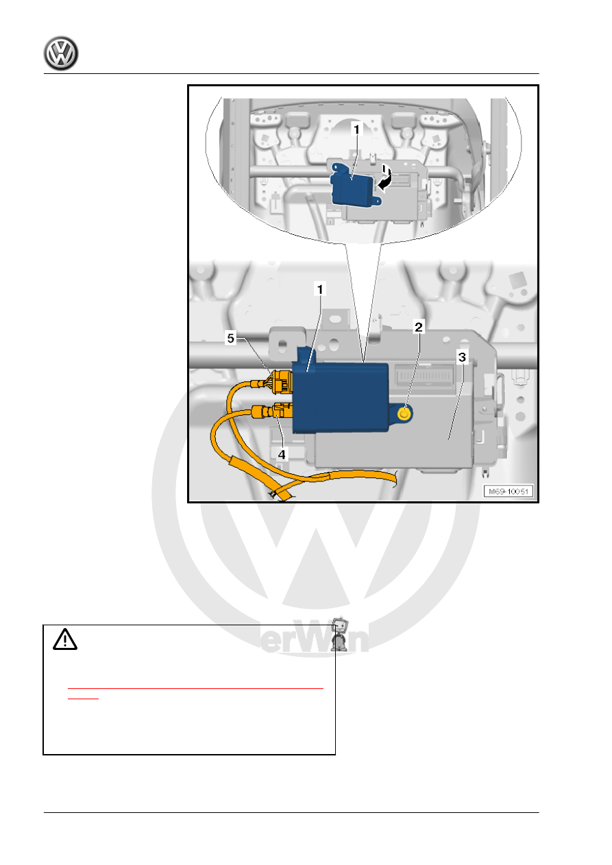
– Disconnect the connectors -4 and 5- from the Passenger Oc‐

cupant Detection System Control Module - J706- -1-.

– Remove the bolt -2-.
– Remove the Passenger Occupant Detection System Control

Module - J706- -1- from the bracket -3- in direction of

-arrow-.

Installing

WARNING

♦ Observe the safety precautions for pyrotechnical compo‐

nents. Refer to

⇒ “1.2 Safety Precautions for Pyrotechnic Components”,

page 3

 .

♦ Before handling pyrotechnic components (for example,

connecting the connector), the person handling it must

“discharge static electricity”. This can be done by touching

the door striker pin, for example.

Installation is performed in reverse order of removal, while noting

the following:

Note

Make sure the connectors are pushed in all the way and that

they engage audibly.

Make sure the wires are not pinched.

It is necessary to perform a basic setting/coding in “Guided

Fault Finding” if the Passenger Occupant Detection System

Control Module - J706- was replaced. Refer to Vehicle Diag‐

nostic Tester .

WARNING

The ignition must be on when connecting the battery. If pyro‐

technic components (for example, airbag, belt tensioner) are

not repaired correctly, they may deploy unintentionally after

connecting battery. There must not be anyone inside the ve‐

hicle when connecting the battery.

– Connect the battery ground cable with the ignition turned on.

Refer to ⇒  Electrical Equipment; Rep. Gr.  27 ; Battery; Bat‐

tery, Disconnecting and Connecting .

WARNING

If the ignition is not switched on after the battery is reconnected

- “indicator lamps in the instrument cluster do not light up” - the

ignition (key/button) may only be switched on when the driver

seat is positioned all the way back.

Note

If the Airbag Indicator Lamp - K75- indicates a fault, check the

DTC memory, erase it and check it again using the Vehicle Di‐

agnostic Tester .

13.4

Passenger Occupant Detection System Control Module - J706- Bracket,

Removing and Installing

Removing
– Remove the Passenger Occupant Detection System Control

Module - J706- . Refer to

⇒ “13.3  Passenger Occupant Detection System Control Mod‐

ule J706 , Removing and Installing”, page 186

 .

Note

The components pictured can vary in form and appearance from the present vehicle. However the assembly

and functionality are identical.

– Remove the clamping pin on the clip -1- and loosen the clip

-1-.

– Remove the bracket -2- from the seat frame -3- in direction of

-arrow-.

Installing
Install in reverse order of removal.

13.5

Required Importer Notification

After installing the new components for the passenger occupant

detection system (passenger occupant detection system pres‐

sure sensor / Passenger Occupant Detection System Control

Module - J706- ), attach the labels (only tear-off strips) for the new

components on the “registration tag 2 for airbag systems”. “Reg‐

istration tag 2 for airbag systems” should be sent to importer for

registration.
The “registration tag 2 for airbag systems” can be printed from the

“Technical Service Handbook”:
ElsaWin
→ Technical Service Handbook (HST)
→ Technical Service Bulletin (TSB)

→ Electrical system
→ Function
→ Passenger protection area
→ Turning off the airbag unit/child seat, installing a set, etc.
→ System 2
The “process ID” and “TPI number” for this procedure can be

found in “Technical Service Handbook 2”:“2022327/1”


Content   ..  383  384  385  386   ..