Volkswagen Golf / Golf GTI / Golf Variant. Manual - part 347


  Index      Volkswagen     Volkswagen Golf / Golf GTI / Golf Variant - service repair manual 2013 year


Search            copyright infringement  


Content   ..  345  346  347  348   ..


Volkswagen Golf / Golf GTI / Golf Variant. Manual - part 347


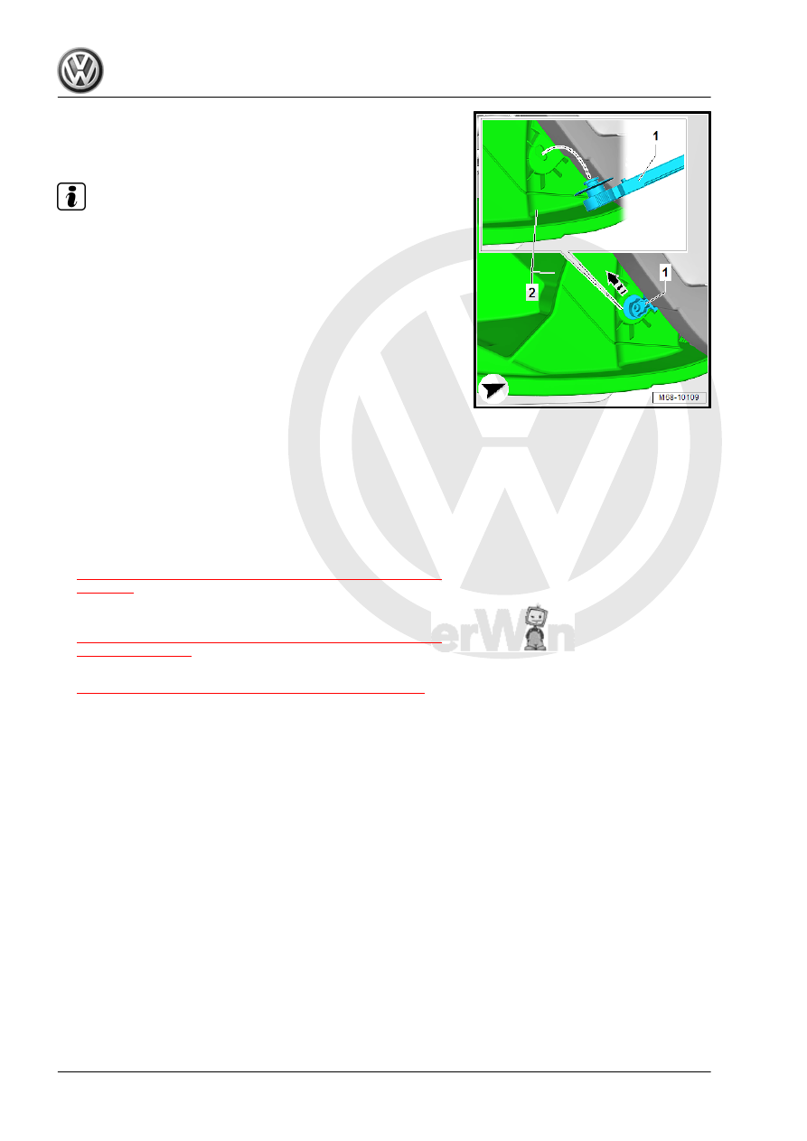
– Move/release the braking element -1- in the direction of the

-arrow- and remove it from the glove compartment lid -2-.

Installing

Note

Check all the fasteners for damage and replace if necessary.

Install in reverse order of removal.

1.17

Glove Compartment, Removing and In‐

stalling

Special tools and workshop equipment required
♦ Torque Wrench 1783 - 2-10Nm - VAG1783-
Removing
– Remove the front passenger instrument panel side cover. Re‐

fer to

⇒ “3.2 Instrument Panel Side Cover, Removing and Installing”,

page 211

 .

– Remove the footwell cover on the front passenger side. Refer

to

⇒ “1.13 Front Passenger Side Footwell Cover, Removing and

Installing”, page 33

 .

– Remove center console. Refer to

⇒ “3.8 Center Console, Removing and Installing”, page 59

– If equipped, remove the Information Electronics Control Mod‐

ule 1 - J794- . Refer to ⇒  Communication; Rep. Gr.  91 ;

Infotainment System; Information Electronics Control Module

1 J794, Removing and Installing .

– Remove the side screw -arrow 1-.
– Open the glove compartment lid and remove the screws

-2 arrows-.

– Unclip the glove compartment from the instrument panel and

remove it just far enough until the hose for the glove compart‐

ment cooling is accessible.

– Remove the glove compartment cooling hose from the glove

compartment.

– Disconnect any connectors from the glove compartment, free

up the wiring guides and remove the glove compartment.

Installing

Note

Check all the fasteners for damage and replace if necessary.

Install in reverse order of removal.
Tightening Specifications
♦ Refer to 

⇒ “1.5 Overview - Glove Compartment”, page 24

♦ Refer to 

⇒ “3.1 Overview - Center Console”, page 53

1.18

Glove Compartment Lid, Removing and

Installing

Removing
– Remove the glove compartment. Refer to

⇒ “1.17 Glove Compartment, Removing and Installing”,

page 36

 .

– Place the glove compartment on a soft surface.
– Move the glove compartment lid into the service position. Re‐

fer to

⇒ “1.15 Glove Compartment Lid Service Position”, page 35

 .

– Drive out the left and right hinge bolts -1- with a punch in di‐

rection of the -arrow B-.

– Remove the glove compartment lid from the glove compart‐

ment.

Installing

Note

Check all the fasteners for damage and replace if necessary.

Install in reverse order of removal.

1.19

Headliner Storage Compartment, Re‐

moving and Installing

Special tools and workshop equipment required
♦ Torque Wrench 1783 - 2-10Nm - VAG1783-
Removing
– Switch off the ignition.
– Unclip the cover -1- from the headliner storage compartment

-3- and remove it.

– Remove the Front Interior Lamp - WX1- -2-. Refer to ⇒  Elec‐

trical Equipment; Rep. Gr.  96 ; Controls; Front Interior Lamp/

Reading Lamp, Removing and Installing .

– If necessary, remove the covers for the interior rearview mir‐

ror. Refer to

⇒ “5.1 Overview - Interior Rearview Mirror”, page 64

 .

– Remove the bolts -1-.

– Remove the headliner storage compartment -2- from the re‐

inforcement frame in the headliner -3-.

Installing

Note

Check all the fasteners for damage and replace if necessary.

Install in reverse order of removal.
Tightening Specifications
♦ Refer to

⇒ “1.6 Overview - Headliner Compartment”, page 25

1.20

Parking Brake Lever Trim, Removing

and Installing

Special tools and workshop equipment required
♦ Trim Removal Wedge - 3409-
Removing
– Unclip the front parking brake lever trim -1- -arrow-.

– Set the parking brake.
– Roll the parking brake lever trim -1- on the parking brake lever

-2- up and over the handle.

– Carefully unclip and remove the parking brake lever trim -1-

on the handle -arrow- using the Trim Removal Wedge - 3409- .

Installing
– Pull the parking brake lever trim -1- over the handle.
– Insert the parking brake lever trim -1- into the groove

-arrow A- in the handle.

– Insert the parking brake lever trim -1- into the center console

and clip it in the front -arrow B-.

1.21

Parking Brake Lever Handle, Removing

and Installing

Special tools and workshop equipment required
♦ Trim Removal Wedge - 3409-
♦ Puller - Unit Injector - T10055-
♦ Assembly Tool - T10488-
Removing
– Remove the parking brake lever trim. Refer to

⇒ “1.20 Parking Brake Lever Trim, Removing and Installing”,

page 38

 .

– Position the Puller - Unit Injector - T10055- -1- on the side of

the handle -2-.

– Remove the handle -2- from the parking brake lever -3- using

the Puller - Unit Injector - T10055- .

Installing

WARNING

Do not re-use the handle for the parking brake lever.

– Set the parking brake.


Content   ..  345  346  347  348   ..