Volkswagen Golf / Golf GTI / Golf Variant. Manual - part 298


  Index      Volkswagen     Volkswagen Golf / Golf GTI / Golf Variant - service repair manual 2013 year


Search            copyright infringement  


Content   ..  296  297  298  299   ..


Volkswagen Golf / Golf GTI / Golf Variant. Manual - part 298


The bumper cover must stay in place and may not be moved dur‐

ing this time.

1.8

Parallel Parking Assist Bracket, Instal‐

ling

Special tools and workshop equipment required
♦ PDC Holder Tool Set - VAS6614B-
♦ Thermal Clip Bonder Kit - VAS6872-
♦ Thermal Clip Bonder Kit - Hand Set - VAS6872/1-
♦ Thermal Clip Bonder Kit - Clip, M-shaped - VAS6872/3-
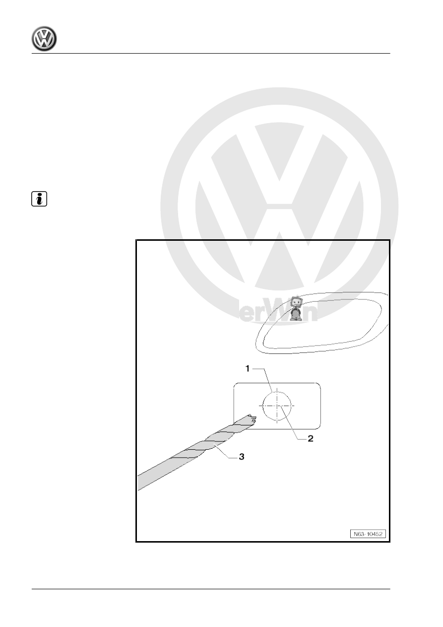
Bracket, Installing

Note

After the bumper cover is painted, install the brackets.

The four markings for the bracket -1- are found on the inside of

the bumper cover.

– Determine the central point -2-, if not already present.
– Drill the holes from the inside outward with the drill -3- supplied

in the tool kit.

– Position the hole stamper with the bolt head -1-, washer -2-

and counterholder -3- on the inside of the bumper cover -5-.

– Position the iron punch -4- almost up to the bumper cover.
– Push the iron punch -4- onto the bumper cover.
– Tighten the hole stamper -1-.

Note

The iron punch -4- must not rotate on the bumper cover paint.

– By turning at the bolt head -1-, the iron punch -4- is pulled

through the bumper cover material -5- -arrows-.

– Remove the hole stamper and stamp the next holes.

Note

The spacer on the device must be set very precisely.

If the setting is too low, then the bracket will not be secured

correctly.

If the setting is too high, marks from the clips will accumulate

on the bumper cover.

4 clips are placed on each side. Refer to the image for the

positions.

Attach 3 clips if the clips have beveled sides.

– Secure the -VAS6872/3- in the -VAS6872/1- -arrow a-.

– Set the distance -a- to exactly 3 mm.
– Secure the bracket -2- using -VAS6614/7- or -VAS6614/6- to

the hole -arrow b-.

– Let the clips melt down without pressure -arrow C-. Switch the

device off when the spacer is attached.

– Let it cool down for 10 seconds. Do not move the device during

this.

– Remove the device after the cool-down time position the next

clip.

– Cut off the ends of the clips after all of the clips are positioned.


Content   ..  296  297  298  299   ..