Toyota C-HR (2021 year). Manual in english - part 7


  Index      Toyota     Toyota C-HR (2021 year). Manual in english


Search            copyright infringement  


Content      ..     5      6      7      8     ..


Toyota C-HR (2021 year). Manual in english - part 7


398

6-3. Do-it-yourself maintenance

C-HR_OM_USA_OM10684U

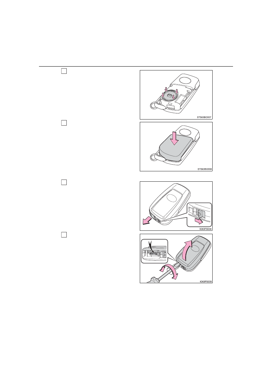
Install the battery cover with the
tab facing up.

Push the entire edge of the battery
cover into the key.

Install the key cover.

Align  the  key  cover  with  the  key
and  then  press  it  straight  into  the
key.
Make  sure  that  the  key  cover  is
securely installed without any gaps
between it and the key.

Vehicles with a smart key system

Release  the  lock  and  take  out
the mechanical key.

Remove the cover.

Use  an  appropriate  sized  flathead
screwdriver.  Forceful  prying  may
deform the cover.
To  prevent  damage  to  the  key,
cover the tip of the screwdriver with
a rag.

4

5

1

2

-------------------------------------------------------------------------------------------------------------------------------------------------------------

399

6-3. Do-it-yourself maintenance

6

Mainten

ance an

d ca

re

C-HR_OM_USA_OM10684U

Remove the depleted battery.

When  removing  the  cover,  if  the
battery cannot be seen due to the
electronic key module attaching to
the  upper  cover,  remove  the  elec-
tronic  key  module  from  the  cover
so  that  the  battery  is  visible  as
shown in the illustration. 
Use  an  appropriate  sized  flathead
screwdriver  when  removing  the
battery.
Insert a new battery with the “+” terminal facing up.

When installing, reverse the steps listed.

Use a CR2032 lithium battery

Batteries can be purchased at your Toyota dealer, local electrical appliance
shops or camera stores.

Replace only with the same or equivalent type recommended by the manu-
facturer.

Dispose of used batteries according to local laws.

If the key battery is depleted 

The following symptoms may occur:

The  smart  key  system  (if  equipped)  and  wireless  remote  control  will  not
function properly.

The operational range will be reduced.

3

4

-------------------------------------------------------------------------------------------------------------------------------------------------------------

400

6-3. Do-it-yourself maintenance

C-HR_OM_USA_OM10684U

WARNING

Removed battery and other parts

These parts are small and if swallowed by a child, they can cause choking.
Keep away from children. Failure to do so could result in death or serious
injury.

NOTICE

For normal operation after replacing the battery

Observe the following precautions to prevent accidents:

Always work with dry hands.
Moisture may cause the battery to rust.

Do not touch or move any other component inside the remote control.

Do not bend either of the battery terminals.

-------------------------------------------------------------------------------------------------------------------------------------------------------------

401

6-3. Do-it-yourself maintenance

6

Mainten

ance an

d ca

re

C-HR_OM_USA_OM10684U

Checking and replacing fuses

Turn the engine switch off.
Open the fuse box cover. 

Engine compartment type A fuse box

While  pushing  the  2  claws,  lift
up the cover.

When closing the cover, make sure
to attach the 2 claws.

Engine compartment type B fuse box

While  pushing  the  3  claws,  lift
up the cover.

When closing the cover, make sure
to attach the 3 claws.

Engine compartment type C fuse box

While  pushing  the  2  claws,  lift
up the cover.

When closing the cover, make sure
to attach the 2 claws.

If any of the electrical components do not operate, a fuse may
have blown. If this happens, check and replace the fuses as nec-
essary.

1

2

-------------------------------------------------------------------------------------------------------------------------------------------------------------

402

6-3. Do-it-yourself maintenance

C-HR_OM_USA_OM10684U

Left side instrument panel

Remove the lid.

Make sure to press the claw during
removal or installation.

Remove  the  fuse  with  the  pull-
out tool.

Only type A fuses can be removed
using the pullout tool.

3

-------------------------------------------------------------------------------------------------------------------------------------------------------------

403

6-3. Do-it-yourself maintenance

6

Mainten

ance an

d ca

re

C-HR_OM_USA_OM10684U

Check if the fuse is blown.

Normal fuse
Blown fuse

Except for type E:
Replace the blown fuse with a new fuse of an appropriate amperage rat-
ing. The amperage rating can be found on the fuse box lid.
Type E:
Contact your Toyota dealer.

4

Type A

Type B

Type C

Type D

Type E

-------------------------------------------------------------------------------------------------------------------------------------------------------------

404

6-3. Do-it-yourself maintenance

C-HR_OM_USA_OM10684U

After a fuse is replaced

If the lights do not turn on even after the fuse has been replaced, a bulb may
need replacement. (

P. 407)

If the replaced fuse blows again, have the vehicle inspected by your Toyota
dealer.

If there is an overload in a circuit

The fuses are designed to blow, protecting the wiring harness from damage.

When replacing light bulbs

Toyota recommends that you use genuine Toyota products designed for this
vehicle. Because certain bulbs are connected to circuits designed to prevent
overload,  non-genuine  parts  or  parts  not  designed  for  this  vehicle  may  be
unusable.

WARNING

To prevent system breakdowns and vehicle fire

Observe the following precautions.
Failure to do so may cause damage to the vehicle, and possibly a fire or
injury.

Never use a fuse of a higher amperage rating than that indicated, or use
any other object in place of a fuse.

Always use a genuine Toyota fuse or equivalent.
Never replace a fuse with a wire, even as a temporary fix.

Do not modify the fuses or fuse boxes.

NOTICE

Before replacing fuses

Have  the  cause  of  electrical  overload  determined  and  repaired  by  your
Toyota dealer as soon as possible.

-------------------------------------------------------------------------------------------------------------------------------------------------------------

405

6-3. Do-it-yourself maintenance

6

Mainten

ance an

d ca

re

C-HR_OM_USA_OM10684U

Headlight aim (vehicles with front fog 

lights)

Adjustment bolt A
Adjustment bolt B

Make  sure  the  vehicle  has  a  full  tank  of  gasoline  and  the  area
around the headlight is not deformed.
Park the vehicle on level ground.
Sit in the driver’s seat.
Bounce the vehicle several times.

Vertical movement adjusting bolts

Before checking the headlight aim

1

2

3

4

-------------------------------------------------------------------------------------------------------------------------------------------------------------

406

6-3. Do-it-yourself maintenance

C-HR_OM_USA_OM10684U

Using  a  Phillips-head  screw-
driver, turn bolt A in either direc-
tion.

Remember  the  turning  direction
and the number of turns.

Turn bolt B the same number of
turns and in the same direction
as step 

.

If the headlight cannot be adjusted
using this procedure, take the vehi-
cle to your Toyota dealer to adjust
the headlight aim.

Adjusting the headlight aim

1

2

1

-------------------------------------------------------------------------------------------------------------------------------------------------------------

407

6-3. Do-it-yourself maintenance

6

Mainten

ance an

d ca

re

C-HR_OM_USA_OM10684U

Light bulbs

Check the wattage of the light bulb to be replaced. (

P. 483)

Front

Front turn signal lights (bulb type)
Front side marker lights (bulb type)
Side turn signal lights

You may replace the following bulbs yourself. The difficulty level
of replacement varies depending on the bulb. If necessary bulb
replacement  seems  difficult  to  perform,  contact  your  Toyota
dealer.
For more information about replacing other light bulbs, contact
your Toyota dealer.

Preparing for light bulb replacement

Bulb locations

-------------------------------------------------------------------------------------------------------------------------------------------------------------

408

6-3. Do-it-yourself maintenance

C-HR_OM_USA_OM10684U

Rear

Rear side marker lights
Rear turn signal lights
Back-up lights
License plate lights

-------------------------------------------------------------------------------------------------------------------------------------------------------------

409

6-3. Do-it-yourself maintenance

6

Mainten

ance an

d ca

re

C-HR_OM_USA_OM10684U

Front side marker lights (bulb type)

Turn  the  bulb  base  counter-
clockwise.

Remove the light bulb.

When installing, reverse the steps listed.

Front turn signal lights (bulb type)

Turn  the  bulb  base  counter-
clockwise.

Remove the light bulb.

When installing, reverse the steps listed.

Replacing light bulbs

1

2

3

1

2

3

-------------------------------------------------------------------------------------------------------------------------------------------------------------

410

6-3. Do-it-yourself maintenance

C-HR_OM_USA_OM10684U

Rear turn signal lights and rear side marker lights

Open  the  back  door  and
remove the cover.

To  prevent  damaging  the  vehi-
cle,  wrap  the  flathead  screw-
driver with a tape.

Remove  the  2  screws  and
pull  the  light  unit  toward  the
rear of the vehicle to remove
it.

Turn  the  bulb  base  counter-
clockwise.

Rear turn signal lights
Rear side marker lights

Remove the light bulb.

Rear turn signal lights
Rear side marker lights

When  installing  the  light  bulb,  install  by  conducting 

  and 

with the directions reversed.

1

2

3

4

5

3

4

-------------------------------------------------------------------------------------------------------------------------------------------------------------

411

6-3. Do-it-yourself maintenance

6

Mainten

ance an

d ca

re

C-HR_OM_USA_OM10684U

Install the lamp assembly.

Align  the  guide  (

)  and  pins

(

) on the lamp assembly with

the mounting when installing it.

Install the 2 screws.

Install the cover.

6

7

8

-------------------------------------------------------------------------------------------------------------------------------------------------------------

412

6-3. Do-it-yourself maintenance

C-HR_OM_USA_OM10684U

Back-up lights

Open  the  back  door  and
remove the cover.

To  prevent  damaging  the  vehi-
cle,  wrap  the  flathead  screw-
driver with a tape.

Turn  the  bulb  base  counter-
clockwise.

Remove the light bulb.

When installing, reverse the steps listed.

1

2

3

4

-------------------------------------------------------------------------------------------------------------------------------------------------------------

413

6-3. Do-it-yourself maintenance

6

Mainten

ance an

d ca

re

C-HR_OM_USA_OM10684U

License plate lights

Open  the  back  door  and
remove the cover.

To  prevent  damaging  the  vehi-
cle,  wrap  the  flathead  screw-
driver with a tape.

Turn  the  bulb  base  counter-
clockwise.

Remove the light bulb.

When installing, reverse the steps listed.

1

2

3

4

-------------------------------------------------------------------------------------------------------------------------------------------------------------

414

6-3. Do-it-yourself maintenance

C-HR_OM_USA_OM10684U

Side turn signal lights

Insert  a  flathead  screwdriver
and  release  the  claw  for  the
outside  rear  view  mirror
cover.

To  prevent  damaging  the  vehi-
cle,  wrap  the  flathead  screw-
driver with a tape.

Release  the  cover  claws
spanning  over  the  entire
perimeter.

Release the claw of  the bot-
tom  part  of  the  cover  and
then remove the cover.

1

Claw

2

3

-------------------------------------------------------------------------------------------------------------------------------------------------------------

415

6-3. Do-it-yourself maintenance

6

Mainten

ance an

d ca

re

C-HR_OM_USA_OM10684U

Insert  a  flathead  screwdriver
and  remove  the  lens  to  the
outside.

Remove the  socket from  the
side turn signal light housing.

Remove the bulb.

Replace  the  bulb  and  install
the  socket  to  the  side  turn
signal light housing.

Align  the  grooves  of  the  socket
to the side turn signal light hous-
ing.

4

5

6

7

-------------------------------------------------------------------------------------------------------------------------------------------------------------

416

6-3. Do-it-yourself maintenance

C-HR_OM_USA_OM10684U

Install the lens.

Insert the claw of the lens.
Attach the lens.

Arrange the wire harness on the
back side of the lens.

Insert the claw of the cover.

Attach  the  claw  on  the  bot-
tom part of the cover.

8

9

10

-------------------------------------------------------------------------------------------------------------------------------------------------------------

417

6-3. Do-it-yourself maintenance

6

Mainten

ance an

d ca

re

C-HR_OM_USA_OM10684U

Attach the cover claws span-
ning  over  the  entire  perime-
ter.

Finally,  confirm  that  the  outside
claw is securely fitted.

Replacing the following bulbs

If any of the lights listed below has burnt out, have it replaced by
your Toyota dealer.

Headlights

Parking lights/daytime running lights

Front turn signal lights (vehicles with LED type)

Front side marker lights (vehicles with LED type)

Front fog lights

Stop/tail lights

High mounted stoplight

Outer mirror illumination (if equipped)

11

-------------------------------------------------------------------------------------------------------------------------------------------------------------

418

6-3. Do-it-yourself maintenance

C-HR_OM_USA_OM10684U

LED light bulbs

The following lights consist of a number of LEDs. If any of the LEDs burns
out, take your vehicle to your Toyota dealer to have the light replaced.

Headlights

Parking lights/daytime running lights

Front turn signal lights (vehicles with LED type)

Front side marker lights (vehicles with LED type)

Front fog lights 

Stop/tail lights

High mounted stoplight

Outer mirror illumination (if equipped)

Condensation build-up on the inside of the lens

Temporary condensation build-up on the inside of the headlight lens does not
indicate a malfunction.
Contact your Toyota dealer for more information in the following situations:

Large drops of water have built up on the inside of the lens.

Water has built up inside the headlight.

When replacing light bulbs

P. 404

-------------------------------------------------------------------------------------------------------------------------------------------------------------

419

6-3. Do-it-yourself maintenance

6

Mainten

ance an

d ca

re

C-HR_OM_USA_OM10684U

WARNING

Replacing light bulbs

Turn  off  the  lights.  Do  not  attempt  to  replace  the  bulb  immediately  after
turning off the lights. 
The bulbs become very hot and may cause burns.

Do not touch the glass portion of the light bulb with bare hands. When it is
unavoidable to hold the glass portion, use and hold with a clean dry cloth
to avoid getting moisture and oils on the bulb.
Also, if the bulb is scratched or dropped, it may blow out or crack.

Fully install light bulbs and any parts used to secure them. Failure to do so
may result in heat damage, fire, or water entering the headlight unit. This
may damage the headlights or cause condensation to build up on the lens.

Do  not  attempt  to  repair  or  disassemble  light  bulbs,  connectors,  electric
circuits or component parts.
Doing so may result in death or serious injury due to electric shock.

To prevent damage or fire 

Make sure bulbs are fully seated and locked.

Check the wattage of the bulb before installing to prevent heat damage.

-------------------------------------------------------------------------------------------------------------------------------------------------------------

420

6-3. Do-it-yourself maintenance

C-HR_OM_USA_OM10684U

-------------------------------------------------------------------------------------------------------------------------------------------------------------

421

7

When trouble arises

C-HR_OM_USA_OM10684U

7-1. Essential information

Emergency flashers .......... 422
If your vehicle has to be 

stopped in 
an emergency ................. 423

If the vehicle is 

trapped in rising water..... 425

7-2. Steps to 

take in an emergency

If your vehicle needs to be 

towed .............................. 426

If you think 

something is wrong......... 432

Fuel pump shut off 

system ............................ 433

If a warning light turns on or 

a warning buzzer 
sounds ............................ 434

If a warning message is 

displayed......................... 444

If you have a flat tire.......... 449
If the engine will not 

start................................. 460

If the electronic key does not 

operate properly 
(vehicles with a 
smart key system)........... 462

If the vehicle battery is 

discharged ...................... 465

If your vehicle overheats ... 470
If the vehicle becomes 

stuck ............................... 473

-------------------------------------------------------------------------------------------------------------------------------------------------------------

422

7-1. Essential information

C-HR_OM_USA_OM10684U

Emergency flashers

Press the switch.

All the turn signal lights will flash.
To  turn  them  off,  press  the  switch
once again.

Emergency flashers

If  the  emergency  flashers  are  used  for  a  long  time  while  the  engine  is  not
operating, the battery may discharge.

The emergency flashers are used to warn other drivers when the
vehicle has to be stopped in the road due to a breakdown, etc.

-------------------------------------------------------------------------------------------------------------------------------------------------------------

423

7-1. Essential information

C-HR_OM_USA_OM10684U

7

Wh
en tro

uble

 a

ris

es

If your vehicle has to be stopped in an 

emergency

Steadily step on the brake pedal with both feet and firmly depress it.

Do  not  pump  the  brake  pedal  repeatedly  as  this  will  increase  the  effort
required to slow the vehicle.

Shift the shift lever to N.

If the shift lever is shifted to N
After slowing down, stop the vehicle in a safe place by the road.
Stop the engine.

If the shift lever cannot be shifted to N
Keep depressing the brake pedal with both feet to reduce vehicle
speed as much as possible.

Only in an emergency, such as if it becomes impossible to stop
the vehicle in the normal way, stop the vehicle using the follow-
ing procedure:

1

2

3

4

3

-------------------------------------------------------------------------------------------------------------------------------------------------------------

424

7-1. Essential information

C-HR_OM_USA_OM10684U

Vehicles  without  a  smart  key
system:  Stop  the  engine  by
turning the engine switch to the
“ACC” position.

Vehicles  with  a  smart  key  sys-
tem: To  stop  the  engine,  press
and  hold  the  engine  switch  for
2 consecutive seconds or more,
or  press  it  briefly  3  times  or
more in succession.

Stop the vehicle in a safe place by the road.

4

Press and hold for 2 seconds or 
more, or press briefly 3 times or 
more

4

WARNING

If the engine has to be turned off while driving

Power  assist  for  the  brakes  and  steering  wheel  will  be  lost,  making  the
brake  pedal  harder  to  depress  and  the  steering  wheel  heavier  to  turn.
Decelerate as much as possible before turning off the engine.

Vehicles without a smart key system: Never attempt to remove the key, as
doing so will lock the steering wheel.

5

-------------------------------------------------------------------------------------------------------------------------------------------------------------

425

7-1. Essential information

C-HR_OM_USA_OM10684U

7

Wh
en tro

uble

 a

ris

es

If the vehicle is trapped in rising water

Remove the seat belt first.

If the door can be opened, open the door and exit the vehicle.

If  the  door  cannot  be  opened,  open  the  window  using  the  power
window switch and exit the vehicle through the window.

If  the  window  cannot  be  opened  using  the  power  window  switch,
remain calm, wait until the water level inside the vehicle rises to the
point that the water pressure inside of the vehicle equals the water
pressure outside of the vehicle, and then open the door and exit the
vehicle.

In the event the vehicle is submerged in water, remain calm and
perform the following.

WARNING

Using an emergency hammer

*

 for emergency escape

The front side windows and rear side windows, as well as the rear window
can be shattered with an emergency hammer

*

 used for emergency escape.

However, an emergency hammer cannot shatter the windshield as it is lam-
inated glass.

*

: Contact your Toyota dealer or aftermarket accessory manufacturer for fur-

ther information about an emergency hammer.

Escaping the vehicle from the window

There are cases where escaping the vehicle from the window is not possi-
ble due to seating position, passenger body type, etc. 
When  using  an  emergency  hammer,  consider  your  seat  location  and  the
size  of  the  window  opening  to  ensure  that  the  opening  is  accessible  and
large enough to escape.

-------------------------------------------------------------------------------------------------------------------------------------------------------------

426

7-2. Steps to take in an emergency

C-HR_OM_USA_OM10684U

If your vehicle needs to be towed

The following may indicate a problem with your transmission. Contact
your Toyota dealer or commercial towing service before towing.

The engine is running but the vehicle does not move.

The vehicle makes an abnormal sound.

If  towing  is  necessary,  we  recommend  having  your  vehicle
towed  by  your  Toyota  dealer  or  commercial  towing  service,
using a wheel-lift type truck or flatbed truck.
Use a safety chain system for all towing, and abide by all state/
provincial and local laws.

Situations when it is necessary to contact dealers before towing

Towing with a wheel-lift type truck

From the front

From the rear

Release the parking brake.
Turn automatic mode off. 
(

P. 196)

Use  a  towing  dolly  under  the
front wheels.

-------------------------------------------------------------------------------------------------------------------------------------------------------------

427

7-2. Steps to take in an emergency

7

Wh
en tro

uble

 a

ris

es

C-HR_OM_USA_OM10684U

When using a flat-bed truck to transport the vehicle, use tire strapping
belts.  Refer  to  the  owner’s  manual  of  the  flat-bed  truck  for  the  tire
strapping method.
Vehicles  without  a  smart  key  system:  In  order  to  suppress  vehicle
movement  during  transportation,  set  the  parking  brake  and  turn  the
engine switch to the “LOCK” position.
Vehicles with a smart key system: In order to suppress vehicle move-
ment during transportation, set the parking brake and turn the engine
switch off.

If a tow truck is not available in an emergency, your vehicle may be
temporarily towed using cables or chains secured to the emergency
towing eyelets. This should only be attempted on hard surfaced roads
for at most 50 miles (80 km) at under 18 mph (30 km/h). 
A driver must be in the vehicle to steer and operate the brakes. The
vehicle’s  wheels,  drivetrain,  axles,  steering  and  brakes  must  be  in
good condition. 

Using a flatbed truck

Emergency towing

-------------------------------------------------------------------------------------------------------------------------------------------------------------

428

7-2. Steps to take in an emergency

C-HR_OM_USA_OM10684U

To have your vehicle towed by another vehicle, the towing eyelet must
be installed to your vehicle. Install the towing eyelet using the follow-
ing procedure.

Take out the wheel nut wrench and towing eyelet. (

P. 450)

Remove the eyelet cover using
a flathead screwdriver.

To  protect  the  bodywork,  place  a
rag  between  the  screwdriver  and
the  vehicle  body  as  shown  in  the
illustration.

Insert the towing eyelet into the
hole  and  tighten  partially  by
hand.

Tighten down the towing eyelet
securely  using  a  wheel  nut
wrench or hard metal bar.

Emergency towing procedure

1

2

3

4

-------------------------------------------------------------------------------------------------------------------------------------------------------------

429

7-2. Steps to take in an emergency

7

Wh
en tro

uble

 a

ris

es

C-HR_OM_USA_OM10684U

Securely attach cables or chains to the towing eyelet.

Take care not to damage the vehicle body.

Vehicles without a smart key system: Enter the vehicle being towed
and start the engine.

If the engine does not start, turn the engine switch to the “ON” position.

Vehicles  with  a  smart  key  system:  Enter  the  vehicle  being  towed
and start the engine.

If the engine does not start, turn the engine switch to IGNITION ON mode.

Shift the shift lever to N and release the parking brake. 
Turn automatic mode off. (

P. 196)

When the shift lever cannot be shifted: 

P. 193

While towing

If the engine is not running, the power assist for the brakes and steering will
not function, making steering and braking more difficult.

Wheel nut wrench

Wheel nut wrench is installed in the luggage compartment. (

P. 450)

5

6

7

-------------------------------------------------------------------------------------------------------------------------------------------------------------

430

7-2. Steps to take in an emergency

C-HR_OM_USA_OM10684U

WARNING

Observe the following precautions. 
Failure to do so may result in death or serious injury.

When towing the vehicle

While towing

When  towing  using  cables  or  chains,  avoid  sudden  starts,  etc.,  which
place excessive stress on the towing eyelets, cables or chains. The towing
eyelets,  cables  or  chains  may  become  damaged,  broken  debris  may  hit
people, and cause serious damage.

Vehicles without a smart key system: Do not turn the engine switch to the
“LOCK” position.
There is a possibility that the steering wheel is locked and cannot be oper-
ated.

Vehicles with a smart key system: Do not turn the engine switch off.
There is a possibility that the steering wheel is locked and cannot be oper-
ated.

Installing towing eyelets to the vehicle

Make sure that towing eyelets are installed securely. 
If not securely installed, towing eyelets may come loose during towing.

Be sure to transport the vehicle with the
front wheels raised or with all four wheels
raised  off  the  ground.  If  the  vehicle  is
towed  with  the  front  wheels  contacting
the  ground,  the  drivetrain  and  related
parts may be damaged.

-------------------------------------------------------------------------------------------------------------------------------------------------------------

431

7-2. Steps to take in an emergency

7

Wh
en tro

uble

 a

ris

es

C-HR_OM_USA_OM10684U

NOTICE

Towing with a sling-type truck

To prevent damage to the vehicle when towing using a wheel-lift type
truck

Vehicles without a smart key system: Do not tow the vehicle from the rear
when the engine switch is in the “LOCK” position or the key is removed.
The steering lock mechanism is not strong enough to hold the front wheels
straight.

Vehicles  with  a  smart  key  system:  Do  not  tow  the  vehicle  from  the  rear
when the engine switch is off. The steering lock mechanism is not strong
enough to hold the front wheels straight.

When raising the vehicle, ensure adequate ground clearance for towing at
the  opposite  end  of  the  raised  vehicle.  Without  adequate  clearance,  the
vehicle could be damaged while being towed.

To prevent damage to the vehicle when towing with a sling-type truck

Do not tow with a sling-type truck, either from the front or rear.

To prevent damage to the vehicle during emergency towing

Do not secure cables or chains to the suspension components.

Do not tow with a sling-type truck to pre-
vent body damage.

-------------------------------------------------------------------------------------------------------------------------------------------------------------

432

7-2. Steps to take in an emergency

C-HR_OM_USA_OM10684U

If you think something is wrong

Fluid leaks under the vehicle.
(Water dripping from the air conditioning after use is normal.)

Flat-looking tires or uneven tire wear

Engine coolant temperature gauge needle continually points higher
than normal.

Changes in exhaust sound

Excessive tire squeal when cornering

Strange noises related to the suspension system

Pinging or other noises related to the engine

Engine misses, stumbling or running roughly

Appreciable loss of power

Vehicle pulls heavily to one side when braking

Vehicle pulls heavily to one side when driving on a level road

Loss of brake effectiveness, spongy feeling, pedal almost touches
the floor

If you notice any of the following symptoms, your vehicle proba-
bly  needs  adjustment  or  repair.  Contact  your  Toyota  dealer  as
soon as possible.

Visible symptoms

Audible symptoms

Operational symptoms

-------------------------------------------------------------------------------------------------------------------------------------------------------------

433

7-2. Steps to take in an emergency

C-HR_OM_USA_OM10684U

7

Wh
en tro

uble

 a

ris

es

Fuel pump shut off system

Follow the procedure below to restart the engine after the system is
activated.

Vehicles without a smart key system
Turn the engine switch to the “ACC” or “LOCK” position.
Restart the engine.

Vehicles with a smart key system
Turn the engine switch to ACCESSORY mode or turn it off.
Restart the engine.

To  minimize  the  risk  of  fuel  leakage  when  the  engine  stalls  or
when  an  airbag  inflates  upon  collision,  the  fuel  pump  shut  off
system stops the supply of fuel to the engine.

NOTICE

Before starting the engine

Inspect the ground under the vehicle.
If you find that fuel has leaked onto the ground, the fuel system has been
damaged and is in need of repair. Do not restart the engine.

1

2

1

2

-------------------------------------------------------------------------------------------------------------------------------------------------------------

434

7-2. Steps to take in an emergency

C-HR_OM_USA_OM10684U

If a warning light turns on or a warning 

buzzer sounds

Calmly perform the following actions if any of the warning lights
comes  on  or  flashes.  If  a  light  comes  on  or  flashes,  but  then
goes off, this does not necessarily indicate a malfunction in the
system.  However,  if  this  continues  to  occur,  have  the  vehicle
inspected by your Toyota dealer.

Warning light and warning buzzer list

Warning light

Warning light/Details/Actions

(U.S.A.)

(Red) (Canada)

Brake system warning light (warning buzzer)

Indicates that:
• Low brake fluid; or
• The brake system is malfunctioning.

Immediately stop the vehicle in a safe place and con-
tact your Toyota dealer
Continuing to drive the vehicle may be dangerous.

*

1

Low engine oil pressure warning light (warning buzzer)

Indicates abnormal engine oil pressure
The warning light may come on if the engine oil pressure
is too low.
A buzzer also sounds.

Immediately stop the vehicle in a safe place and con-
tact your Toyota dealer 
Continuing to drive the vehicle may be dangerous.

*

1

Charging system warning light

Indicates a malfunction in the vehicle’s charging system

Immediately stop the vehicle in a safe place and con-
tact your Toyota dealer

-------------------------------------------------------------------------------------------------------------------------------------------------------------

435

7-2. Steps to take in an emergency

7

Wh
en tro

uble

 a

ris

es

C-HR_OM_USA_OM10684U

(U.S.A.)

(Canada)

Malfunction indicator lamp (warning buzzer)

Indicates a malfunction in:
• The electronic engine control system;
• The electronic throttle control system; or
• The electronic continuously variable transmission.

Have  the  vehicle  inspected  by  your  Toyota  dealer
immediately.

SRS warning light

Indicates a malfunction in:
• The SRS airbag system; or
• The seat belt pretensioner system.

Have  the  vehicle  inspected  by  your  Toyota  dealer
immediately.

(U.S.A.)

(Canada)

ABS warning light

Indicates a malfunction in:
• The ABS; or
• The brake assist system.

Have  the  vehicle  inspected  by  your  Toyota  dealer
immediately.

(Red/yellow)

Electric  power  steering  system  warning  light  (warning
buzzer)

Indicates a malfunction in the EPS (Electric Power Steer-
ing) system

Have  the  vehicle  inspected  by  your  Toyota  dealer
immediately.

(Flashes)

“RCTA OFF” indicator (if equipped)

When a buzzer sounds:
Indicates a malfunction in the RCTA (Rear Crossing Traffic
Alert) function

Have  the  vehicle  inspected  by  your  Toyota  dealer
immediately.

When a buzzer does not sound:
Indicates that the rear bumper around the radar sensor is
covered with dirt, etc. (

P. 286)

Follow  the  instructions  displayed  on  the  multi-infor-
mation display. (

P. 293)

Warning light

Warning light/Details/Actions

-------------------------------------------------------------------------------------------------------------------------------------------------------------

436

7-2. Steps to take in an emergency

C-HR_OM_USA_OM10684U

Slip indicator

Indicates a malfunction in:
• The VSC (Vehicle Stability Control) system;
• The TRAC (Traction Control) system; or
• The hill-start assist control system.
The light will flash when the VSC or the TRAC is operat-
ing. (

P. 301)

Have  the  vehicle  inspected  by  your  Toyota  dealer
immediately.

(Yellow)

Brake system warning light

Indicates a malfunction in the electric parking brake

Have  the  vehicle  inspected  by  your  Toyota  dealer
immediately.

*

1

(Flashes)

Brake hold operated indicator

Indicates a malfunction in the brake hold system

Have  the  vehicle  inspected  by  your  Toyota  dealer
immediately.

*

1

(Orange)

LTA indicator (warning buzzer)

Indicates a malfunction in the LTA (Lane Tracing Assist)

Follow  the  instructions  displayed  on  the  multi-infor-
mation display. (

P. 260)

(Flashes or 
illuminates)

PCS warning light

When a buzzer sounds simultaneously:
Indicates a malfunction has occurred in the PCS (Pre-Collision
System).

Have  the  vehicle  inspected  by  your  Toyota  dealer
immediately.

When a buzzer does not sound: 
The PCS (Pre-Collision System) has become temporarily
unavailable, corrective action may be necessary.

Follow  the  instructions  displayed  on  the  multi-infor-
mation display. (

P. 229, 444)

If the PCS (Pre-Collision System) or VSC (Vehicle Stability
Control) system is disabled, the PCS warning light will illu-
minate.

P. 245

*

2

(Flashes) (U.S.A.)

(Flashes) (Canada)

Parking brake indicator (warning buzzer)

It is possible that the parking brake is not fully engaged or
released

Operate the parking brake switch once again.

This  light  comes  on  when  the  parking  brake  is  not
released. If the light turns off after the parking brake is fully
released, the system is operating normally.

Warning light

Warning light/Details/Actions

-------------------------------------------------------------------------------------------------------------------------------------------------------------

437

7-2. Steps to take in an emergency

7

Wh
en tro

uble

 a

ris

es

C-HR_OM_USA_OM10684U

Low fuel level warning light

Indicates  that  remaining  fuel  is  approximately  2.0 gal.
(7.5 L, 1.6 Imp.gal.) or less

Refuel the vehicle.

*

3

Driver’s  and  front  passenger’s  seat  belt  reminder  light
(warning buzzer)

Warns  the  driver  and/or  front  passenger  to  fasten  their
seat belts.

Fasten the seat belt. 
If the front passenger seat is occupied, the front pas-
senger’s seat belt also needs to be fastened to make
the warning light (warning buzzer) off.

*

3

(On the center panel)

Rear  passengers’  seat  belt  reminder  lights  (warning
buzzer)

Warn the rear passengers to fasten their seat belts

Fasten the seat belt.

Tire pressure warning light

When the light comes on:

Low tire inflation pressure such as

• Natural causes (

P. 440)

• Flat tire (

P. 449)

Adjust  the  tire  inflation  pressure  to  the  specified

level. 

The light will turn off after a few minutes. In case

the light does not turn off even if the tire inflation

pressure is adjusted, have the system checked by

your Toyota dealer.

When the light comes on after blinking for 1 minute:

Malfunction in the tire pressure warning system 

(

P. 440)

Have the system checked by your Toyota dealer.

*

1

High engine coolant temperature warning light (warning
buzzer)

Indicates that the engine coolant temperature is too high

P. 470

Warning light

Warning light/Details/Actions

-------------------------------------------------------------------------------------------------------------------------------------------------------------

438

7-2. Steps to take in an emergency

C-HR_OM_USA_OM10684U

*

1

: This light illuminates on the multi-information display.

*

2

: Parking brake engaged warning buzzer:

A  buzzer  will  sound  if  the  vehicle  is  driven  at  a  speed  of  approximately
3 mph (5 km/h) or more.

*

3

: Driver’s seat belt warning buzzer: 

The driver’s seat belt warning buzzer sounds to alert the driver that his or
her seat belt is not fastened. Once the engine switch is turned to the “ON”
position (vehicles without smart key system) or IGNITION ON mode (vehi-
cles  with  smart  key  system),  the  buzzer  sounds.  If  the  seat  belt  is  still
unfastened,  the  buzzer  sounds  intermittently  for  a  certain  period  of  time
after the vehicle reaches a certain speed.

Front passenger’s seat belt warning buzzer: 
The  front  passenger’s  seat  belt  warning  buzzer  sounds  to  alert  the  front
passenger that his or her seat belt is not fastened. If the seat belt is unfas-
tened, the buzzer sounds intermittently for a certain period of time after the
vehicle reaches a certain speed.

Rear passengers’ seat belt warning buzzer: 
The  rear  passengers’  seat  belt  warning  buzzer  sounds  to  alert  the  rear
passenger that his or her seat belt is not fastened. If the seat belt is unfas-
tened,  the  buzzer sounds  intermittently for  a  certain period  of time,  after
the seat belt is fastened and unfastened and the vehicle reaches a certain
speed.

*

1

Brake Override System

Indicates that the accelerator and brake pedals are being
depressed  simultaneously,  and  the  Brake  Override  Sys-
tem is operating.

Release the accelerator pedal and depress the brake
pedal.

Indicates  a  malfunction  in  the  Brake  Override  System
(with warning buzzer)

Have  the  vehicle  inspected  by  your  Toyota  dealer
immediately. 

Drive-Start Control

Indicates  that  the  shift  position  was  changed  and  Drive-
Start Control was operated while depressing the accelera-
tor pedal. (with warning buzzer)

Momentarily release the accelerator pedal.

Indicates a malfunction in the Drive-Start Control system
(with warning buzzer)

Have  the  vehicle  inspected  by  your  Toyota  dealer
immediately.

Warning light

Warning light/Details/Actions

-------------------------------------------------------------------------------------------------------------------------------------------------------------

439

7-2. Steps to take in an emergency

7

Wh
en tro

uble

 a

ris

es

C-HR_OM_USA_OM10684U

SRS warning light

This warning light system monitors the airbag sensor assembly, front impact
sensors,  side  impact  sensors  (front  door),  side  impact  sensors  (front),  side
impact sensors (rear), driver’s seat position sensor, driver’s seat belt buckle
switch, front passenger occupant classification system, “AIR BAG ON” indica-
tor  light,  “AIR  BAG  OFF”  indicator  light,  front  passenger’s  seat  belt  buckle
switch,  seat  belt  pretensioners,  airbags,  interconnecting  wiring  and  power
sources. (

P. 34)

Electric power steering system warning light (warning buzzer)

When  the  battery  charge  becomes  insufficient  or  the  voltage  temporarily
drops, the electric power steering system warning light may come on and the
warning buzzer may sound.

If the malfunction indicator lamp comes on while driving

For some models, the malfunction indicator lamp will come on if the fuel tank
becomes completely empty. If the fuel tank is empty, refuel the vehicle imme-
diately. The malfunction indicator lamp will go off after several trips. 
If the malfunction indicator lamp does not go off, contact your Toyota dealer.

Front  passenger  detection  sensor,  seat  belt  reminder  and  warning
buzzer

If luggage is placed on the front passenger seat, the front passenger detec-
tion sensor may cause the warning light to flash and the warning buzzer to
sound even if a passenger is not sitting in the seat.

If a cushion is placed on the seat, the sensor may not detect a passenger,
and the warning light may not operate properly.

Warning light operations for unfastened rear passenger seat belts

When  opening  and  closing  the  rear  door,  the  warning  light  comes  on  for
approximately 34 seconds.

When any of the rear seat belts are unfastened, the warning light comes on. 
When the rear doors are opened and closed while the warning light is on,
the warning light will turn off after approximately 34 seconds.

-------------------------------------------------------------------------------------------------------------------------------------------------------------

440

7-2. Steps to take in an emergency

C-HR_OM_USA_OM10684U

When the tire pressure warning light comes on

Inspect the appearance of the tire to check that the tire is not punctured.
If the tire is punctured: 

P. 449

If the tire is not punctured:
Carry out the following procedure after the tire temperature has lowered

sufficiently.

Check the tire inflation pressure and adjust to the appropriate level.

If the warning  light  does not go  out  even after several minutes, check

that the tire inflation pressure is at the specified level and carry out ini-

tialization. (

P. 378)

The  warning  light  may  come  on  again  if  the  above  operations  are  con-

ducted without first allowing the tire temperature to lower sufficiently.

The tire pressure warning light may come on due to natural causes

The tire pressure warning light may come on due to natural causes such

as  natural  air  leaks  and  tire  inflation  pressure  changes  caused  by  tem-

perature. In this case, adjusting the tire inflation pressure will turn off the

warning light (after a few minutes).

When a tire is replaced with a spare tire

The compact spare tire is not equipped with a tire pressure warning valve

and transmitter. If a tire goes flat, the tire pressure warning light will not

turn  off  even  though  the  flat  tire  has  been  replaced  with  the  spare  tire.

Replace the spare tire with the repaired tire and adjust the tire inflation

pressure. The tire pressure warning light will go off after a few minutes.

Conditions  that  the  tire  pressure  warning  system may  not function

properly

P. 381

If the tire pressure warning light frequently comes on after blinking

for 1 minute

If  the  tire  pressure  warning  light  frequently  comes  on  after  blinking  for

1 minute when the engine switch is turned to the “ON” position (vehicles

without  smart  key  system)  or  IGNITION  ON  mode  (vehicles  with  smart

key system), have it checked by your Toyota dealer.

Warning buzzer

In some cases, the buzzer may not be heard because of noisy place or an
audio sound.

-------------------------------------------------------------------------------------------------------------------------------------------------------------

441

7-2. Steps to take in an emergency

7

Wh
en tro

uble

 a

ris

es

C-HR_OM_USA_OM10684U

WARNING

If both the ABS and the brake system warning lights remain on

Stop  your  vehicle  in  a  safe  place  immediately  and  contact  your  Toyota
dealer. The vehicle will become extremely unstable during braking, and the
ABS system may fail, which could cause an accident resulting in death or
serious injury.

When the electric power steering system warning light comes on

When  the  light  comes  on  yellow,  the  assist  to  the  power  steering  is
restricted. When the light comes on red, the assist to the power steering is
lost  and  handling  operations  of  the  steering  wheel  become  extremely
heavy.  When  steering  wheel  operations  are  heavier  than  usual,  grip  the
steering wheel firmly and operate it using more force than usual.

If the tire pressure warning light comes on

Be  sure  to  observe  the  following  precautions.  Failure  to  do  so  could

cause a loss of vehicle control and result in death or serious injury.

Stop your vehicle in a safe place as soon as possible. Adjust the tire

inflation pressure immediately.

If the tire pressure warning light comes on even after tire inflation pres-

sure adjustment, it is probable that you have a flat tire. Check the tires.

If  a  tire  is  flat,  change  it  with  the  spare  tire  and  have  the  flat  tire

repaired by the nearest Toyota dealer.

Avoid abrupt maneuvering and braking. If the vehicle tires deteriorate,

you could lose control of the steering wheel or the brakes.

If a blowout or sudden air leakage should occur

The tire pressure warning system may not activate immediately.

-------------------------------------------------------------------------------------------------------------------------------------------------------------

442

7-2. Steps to take in an emergency

C-HR_OM_USA_OM10684U

WARNING

Maintenance of the tires

Each tire, including the spare (if provided), should be checked monthly

when  cold  and  inflated  to  the  inflation  pressure  recommended  by  the

vehicle  manufacturer  on  the  vehicle  placard  or  tire  inflation  pressure

label (tire and load information label). (If your vehicle has tires of a dif-

ferent size than the size indicated on the vehicle placard or tire inflation

pressure  label  [tire  and  load  information  label],  you  should  determine

the proper tire inflation pressure for those tires.)
As an added safety feature, your vehicle has been equipped with a tire

pressure monitoring system (TPMS-tire pressure warning system) that

illuminates a low tire pressure telltale (tire pressure warning light) when

one  or  more  of  your  tires  is  significantly  under-inflated.  Accordingly,

when  the  low  tire  pressure  telltale  (tire  pressure  warning  light)  illumi-

nates, you should stop and check your tires as soon as possible, and

inflate  them  to  the  proper  pressure.  Driving  on  a  significantly  under-

inflated  tire  causes  the  tire  to  overheat  and  can  lead  to  tire  failure.

Under-inflation also reduces fuel efficiency and tire tread life, and may

affect the vehicle’s handling and stopping ability.
Please note that the TPMS (tire pressure warning system) is not a sub-

stitute for proper tire maintenance, and it is the driver’s responsibility to

maintain  correct  tire  pressure,  even  if  under-inflation  has  not  reached

the level to trigger illumination of the TPMS low tire pressure telltale (tire

pressure warning light).
Your vehicle has also been equipped with a TPMS (tire pressure warn-

ing  system)  malfunction  indicator  to  indicate  when  the  system  is  not

operating properly. The TPMS (tire pressure warning system) malfunc-

tion indicator is combined with the low tire pressure telltale (tire pressure

warning light). When the system detects a malfunction, the telltale will

flash for approximately one minute and then remain continuously illumi-

nated. This sequence will continue upon  subsequent vehicle  start-ups

as long as the malfunction exists. When the malfunction indicator is illu-

minated, the system may not be able to detect or signal low tire pres-

sure as intended.
TPMS (tire pressure warning system) malfunctions may occur for a vari-

ety of reasons, including the installation of replacement or alternate tires

or wheels on the vehicle that prevent the TPMS (tire pressure warning

system)  from  functioning  properly. Always  check  the TPMS  (tire  pres-

sure  warning  system)  malfunction  telltale  after  replacing  one  or  more

tires or wheels on your vehicle to ensure that the replacement or alter-

nate tires and wheels allow the TPMS (tire pressure warning system) to

continue to function properly.

-------------------------------------------------------------------------------------------------------------------------------------------------------------

443

7-2. Steps to take in an emergency

7

Wh
en tro

uble

 a

ris

es

C-HR_OM_USA_OM10684U

NOTICE

To ensure the tire pressure warning system operates properly

Do  not  install  tires  with  different  specifications  or  makers,  as  the  tire

pressure warning system may not operate properly.

-------------------------------------------------------------------------------------------------------------------------------------------------------------

444

7-2. Steps to take in an emergency

C-HR_OM_USA_OM10684U

If a warning message is displayed

Multi-information display

If any of the warning messages are shown again after the following
actions have been performed, contact your Toyota dealer.

The  multi-information  display  shows  warnings  of  system  mal-
functions, incorrectly performed operations, and messages that
indicate  a  need  for  maintenance.  When  a  message  is  shown,
perform the correction procedure appropriate to the message.

-------------------------------------------------------------------------------------------------------------------------------------------------------------

445

7-2. Steps to take in an emergency

7

Wh
en tro

uble

 a

ris

es

C-HR_OM_USA_OM10684U

The warning lights and warning buzzers operate as follows depending
on the content of the message. If a message indicates the need for
inspection  by  a  dealer,  have  the  vehicle  inspected  by  your  Toyota
dealer immediately.

*

: A buzzer sounds the first time a message is shown on the multi-informa-

tion display

Messages and warnings

System 

warning 

light

Warning 

buzzer

*

Warning

Sounds

• Indicates  an  important  situation,  such  as

when a system related to driving is malfunc-
tioning or that danger may result if the correc-
tion procedure is not performed

• Indicates  a  situation,  such  as  when  damage

to the vehicle or danger may result

Comes 

on or 

flashes

Sounds

Indicates an important situation, such as when
the systems shown on the multi-information dis-
play may be malfunctioning

Does not 

sound

• Indicates a condition, such as malfunction of

electrical components, their condition, or indi-
cates the need for maintenance

• Indicates a situation, such as when an opera-

tion  has  been  performed  incorrectly,  or  indi-
cates how to perform an operation correctly

-------------------------------------------------------------------------------------------------------------------------------------------------------------

446

7-2. Steps to take in an emergency

C-HR_OM_USA_OM10684U

Warning messages

The warning messages explained below may differ from the actual messages
according to operation conditions and vehicle specifications.

If  a  message  that  indicates  the  need  for  visiting  your  Toyota  dealer  is
displayed

The system or part shown on the multi-information display is malfunctioning.
Have the vehicle inspected by your Toyota dealer immediately.

If a message about an operation is shown

If a message about an operation of the accelerator pedal or brake pedal is
shown 
A warning message about an operation of the brake pedal may be shown
while the driving assist systems such as PCS (Pre-Collision System) or the
dynamic radar cruise control with full-speed range is operating. If a warning
message is shown, be sure to decelerate the vehicle or follow the instruction
shown on the multi-information display.

A  warning  message  is  shown  when  Brake  Override  System  operates.
(

P. 166)

A warning message is shown when Drive-Start Control operates 
(

P. 166). Follow the instructions on the multi-information display.

If a message about an operation of the engine switch is shown 
An instruction for operation of the engine switch is shown when the incorrect
procedure for starting the engine is performed or the engine switch is oper-
ated incorrectly. Follow the instructions shown on the multi -information dis-
play to operate the engine switch again.

If a message about a shift lever operation is shown 
To prevent the shift lever from being operated incorrectly or the vehicle from
moving unexpectedly, a message that requires shifting the shift lever may
be shown on the multi-information display. In that case, follow the instruction
of the message and shift the shift lever.

If a message or image about an open/close state of a part or replenishment
of a consumable is shown 
Confirm the part indicated by the multi-information display or a warning light,
and  then  perform  the  coping  method  such  as  closing  the  open  door  or
replenishing a consumable.

-------------------------------------------------------------------------------------------------------------------------------------------------------------

447

7-2. Steps to take in an emergency

7

Wh
en tro

uble

 a

ris

es

C-HR_OM_USA_OM10684U

If a message that indicates the need for referring to Owner’s Manual is
displayed

If “Engine Coolant Temperature High.”is shown, follow the instructions 
(

P. 470).

If the following messages are shown, there may be a malfunction. Immedi-
ately stop the vehicle in a safe place and contact your Toyota dealer. Con-
tinuing to drive the vehicle may be dangerous.
• “Braking Power Low.”
• “Charging System Malfunction.”
• “Engine Oil Pressure Low.”

If the following messages are shown, there may be a malfunction. Immedi-
ately have the vehicle inspected by your Toyota dealer.
• “Smart Key System Malfunction.”

If “Engine Oil Level Low. Add or Replace Oil.” is displayed

The engine oil level is low. Check the level of the engine oil, and add if neces-
sary.
This  message  may  appear  if  the  vehicle  is  stopped  on  a  slope.  Move  the
vehicle to a level surface and check to see if the message disappears.

If “Engine Stopped. Steering Power Low.” is displayed

This message is displayed if the engine is stopped while driving.
When  steering  wheel  operations  are  heavier  than  usual,  grip  the  steering
wheel firmly and operate it using more force than usual.

If “Maintenance Required Soon.” is shown (U.S.A. only)

Indicates that all maintenance according to the driven distance on the mainte-
nance schedule

*

 should be performed soon.

Comes on approximately 4500 miles (7200 km) after the message has been
reset.
If necessary, perform maintenance. Please reset the message after the main-
tenance is performed. (

P. 348)

*

: Refer to the separate “Scheduled Maintenance Guide” or “Owner’s Manual

Supplement” for the maintenance interval applicable to your vehicle.

If “Maintenance Required. Visit Your Dealer.” is shown (U.S.A. only)

Indicates that all maintenance is required to correspond to the driven distance
on the maintenance schedule

*

.

Comes on approximately 5000 miles (8000 km) after the message has been
reset.  (The  indicator  will  not  work  properly  unless  the  message  has  been
reset.)
Perform  the  necessary  maintenance.  Please  reset  the  message  after  the
maintenance is performed. (

P. 348)

*

: Refer to the separate “Scheduled Maintenance Guide” or “Owner’s Manual

Supplement” for the maintenance interval applicable to your vehicle.

-------------------------------------------------------------------------------------------------------------------------------------------------------------

448

7-2. Steps to take in an emergency

C-HR_OM_USA_OM10684U

If “A New Key has been Registered. Contact Your Dealer for Details.” is
shown (vehicles with a smart key system)

This message will be displayed each time the driver’s door is opened when
the doors are unlocked from the outside for approximately one week after a
new electronic key has been registered.
If this message is displayed but you have not had a new electronic key regis-
tered,  ask  your Toyota  dealer  to  check  if  an  unknown  electronic  key  (other
than those in your possession) has been registered.

If a message that indicates the malfunction of front camera is displayed

The  following  systems  may  be  suspended  until  the  problem  shown  in  the
message is resolved. (

P. 229, 434)

PCS (Pre-Collision System)

LTA (Lane Tracing Assist)

Dynamic radar cruise control with full-speed range

RSA (Road Sign Assist) (if equipped)

Automatic High Beam

If a message that indicates the malfunction of radar sensor is displayed

The  following  systems  may  be  suspended  until  the  problem  shown  in  the
message is resolved. (

P. 229, 434)

PCS (Pre-Collision System)

LTA (Lane Tracing Assist)

Dynamic radar cruise control with full-speed range

If “Radar Cruise Control Unavailable See Owner’s Manual” is shown

The dynamic radar cruise control with full-speed range system is suspended
temporarily or until the problem shown in the message is resolved. (causes
and coping methods: 

P. 229)

If “Radar Cruise Control unavailable.” is shown

The  dynamic  radar  cruise  control  with  full-speed  range  system  cannot  be
used temporarily. Use the system when it becomes available again.

Warning buzzer

P. 440

-------------------------------------------------------------------------------------------------------------------------------------------------------------

449

7-2. Steps to take in an emergency

C-HR_OM_USA_OM10684U

7

Wh
en tro

uble

 a

ris

es

If you have a flat tire

Stop the vehicle in a safe place on a hard, flat surface.

Set the parking brake.

Shift the shift lever to P.

Stop the engine.

Turn on the emergency flashers. (

P. 422)

Your  vehicle  is  equipped  with  a  spare  tire.  The  flat  tire  can  be
replaced with the spare tire.
For details about tires: 

P. 376

WARNING

If you have a flat tire

Do not continue driving with a flat tire.

Driving even a short distance with a flat tire can damage the tire and the

wheel beyond repair, which could result in an accident.

Before jacking up the vehicle

-------------------------------------------------------------------------------------------------------------------------------------------------------------

450

7-2. Steps to take in an emergency

C-HR_OM_USA_OM10684U

Location of the spare tire, jack and tools

Towing eyelet
Wheel nut wrench
Jack

Jack handle
Spare tire

-------------------------------------------------------------------------------------------------------------------------------------------------------------

451

7-2. Steps to take in an emergency

7

Wh
en tro

uble

 a

ris

es

C-HR_OM_USA_OM10684U

WARNING

Using the tire jack

Observe the following precautions. 

Improper use of the tire jack may cause the vehicle to suddenly fall off

the jack, leading to death or serious injury.

Do not use the tire jack for any purpose other than replacing tires or

installing and removing tire chains.

Only use the tire jack that comes with this vehicle for replacing a flat

tire. 

Do  not  use  it  on  other  vehicles,  and  do  not  use  other  tire  jacks  for

replacing tires on this vehicle.

Do not put any part of your body under the vehicle while it is supported

by the jack.

Do  not  start  the  engine  or  drive  the  vehicle  while  the  vehicle  is  sup-

ported by the jack.

Do not raise the vehicle while someone is inside.

When raising the vehicle, do not put an object on or under the jack.

Do  not  raise  the  vehicle  to  a  height  greater  than  that  required  to

replace the tire.

Use a jack stand if it is necessary to get under the vehicle.

When  lowering  the  vehicle,  make  sure  that  there  is  no-one  near  the

vehicle. If there are people nearby, warn them vocally before lowering.

Put the jack properly in its jack point.

(

P. 453)

-------------------------------------------------------------------------------------------------------------------------------------------------------------

452

7-2. Steps to take in an emergency

C-HR_OM_USA_OM10684U

Remove the deck board. (

P. 331)

Take out the jack.

Remove the deck board. (

P. 331)

Remove the cushion.

Loosen the center fastener that
secures the spare tire.

Taking out the jack

1

2

Taking out the spare tire

1

2

3

WARNING

When storing the spare tire

Be careful not to catch fingers or other body parts between the spare

tire and the body of the vehicle.

-------------------------------------------------------------------------------------------------------------------------------------------------------------

453

7-2. Steps to take in an emergency

7

Wh
en tro

uble

 a

ris

es

C-HR_OM_USA_OM10684U

Chock the tires.

Slightly  loosen  the  wheel  nuts
(one turn).

Turn the tire jack portion 

 by

hand  until  the  center  of  the
recessed  portion  of  the  jack  is
in contact with the center of the
jack point.

Replacing a flat tire

1

Flat tire

Wheel chock positions

Front

Left-hand side

Behind the rear right-hand side tire

Right-hand side

Behind the rear left-hand side tire

Rear

Left-hand side

In front of the front right-hand side tire

Right-hand side

In front of the front left-hand side tire

2

3

-------------------------------------------------------------------------------------------------------------------------------------------------------------

454

7-2. Steps to take in an emergency

C-HR_OM_USA_OM10684U

Assemble  the  jack  handle  and
the wheel nut wrench as shown
in the illustration.

Raise the vehicle until the tire is
slightly raised off the ground.

Remove all the wheel nuts and
the tire.

When  resting  the  tire  on  the

ground, place the tire so that the

wheel  design  faces  up  to  avoid

scratching the wheel surface.

4

5

6

-------------------------------------------------------------------------------------------------------------------------------------------------------------

455

7-2. Steps to take in an emergency

7

Wh
en tro

uble

 a

ris

es

C-HR_OM_USA_OM10684U

WARNING

Replacing a flat tire

Observe the following precautions.

Failure to do so may result in serious injury:
• Do not try to remove the wheel ornament by hand. Take due care in

handling the ornament to avoid unexpected personal injury.

• Do not touch the disc wheels or the area around the brakes immedi-

ately after the vehicle has been driven.

After  the  vehicle  has  been  driven,  the  disc  wheels  and  the  area

around the brakes will be extremely hot. Touching these areas with

hands,  feet  or  other  body  parts  while  changing  a  tire,  etc.,  may

result in burns.

Failure  to  follow  these  precautions  could  cause  the  wheel  nuts  to

loosen and the tire to fall off, resulting in death or serious injury.
• Have  the  wheel  nuts  tightened  with  a  torque  wrench  to  76 ft·lbf

(103 N·m, 10.5 kgf·m) as soon as possible after changing wheels.

• Do not attach a heavily damaged wheel ornament, as it may fly off

the wheel while the vehicle is moving.

• When installing a tire, only use wheel nuts that have been specifi-

cally designed for that wheel.

• If  there  are  any  cracks  or  deformations  in  the  bolt  screws,  nut

threads  or  bolt  holes  of  the  wheel,  have  the  vehicle  inspected  by

your Toyota dealer.

• When  installing  the  wheel  nuts,  be  sure  to  install  them  with  the

tapered ends facing inward.

-------------------------------------------------------------------------------------------------------------------------------------------------------------

456

7-2. Steps to take in an emergency

C-HR_OM_USA_OM10684U

Remove any dirt or foreign mat-
ter from the wheel contact sur-
face.

If  foreign  matter  is  on  the  wheel

contact  surface,  the  wheel  nuts

may loosen while the vehicle is in

motion,  causing  the  tire  to  come

off.

Install  the  tire  and  loosely  tighten  each  wheel  nut  by  hand  by
approximately the same amount.
When  replacing  a  steel  wheel
with  a  steel  wheel,  tighten  the
wheel  nuts  until  the  tapered
portion  comes  into  loose  con-
tact with the disc wheel seat.

When  replacing  an  aluminum
wheel  with  a  steel  wheel,
tighten the wheel nuts until the
tapered  portion  comes  into
loose  contact  with  the  disc
wheel seat.

Lower the vehicle.

Installing the spare tire

1

2

Tapered portion

Disc wheel seat

Tapered portion

Disc wheel seat

3

-------------------------------------------------------------------------------------------------------------------------------------------------------------

457

7-2. Steps to take in an emergency

7

Wh
en tro

uble

 a

ris

es

C-HR_OM_USA_OM10684U

Firmly  tighten  each  wheel  nut
two  or  three  times  in  the  order
shown in the illustration.

Tightening torque:

76 ft·lbf (103 N·m, 10.5 kgf·m)

Stow the flat tire, tire jack and all tools.

The compact spare tire

The  compact  spare  tire  is  identified  by  the  label  “TEMPORARY  USE

ONLY” on the tire sidewall.

Use the compact spare tire temporarily, and only in an emergency.

Make sure to check the tire inflation pressure of the compact spare tire. 

(

P. 482)

After completing the tire change

The tire pressure warning system must be reset. (

P. 378)

When using the compact spare tire

As  the  compact  spare  tire  is  not  equipped  with  a  tire  pressure  warning

valve and transmitter, low inflation pressure of the spare tire will not be

indicated  by  the  tire  pressure  warning  system. Also,  if  you  replace  the

compact spare tire after the tire pressure warning light comes on, the light

remains on.

When the compact spare tire is equipped

The  vehicle  becomes  lower  when  driving  with  the  compact  spare  tire

compared to when driving with standard tires.

If you have a flat front tire on a road covered with snow or ice

Install  the  compact  spare  tire  on  one  of  the  rear  wheels  of  the  vehicle.

Perform the following steps and fit tire chains to the front tires:

Replace a rear tire with the compact spare tire.
Replace the flat front tire with the tire removed from the rear of the vehi-

cle.
Fit tire chains to the front tires.

4

5

1

2

3

-------------------------------------------------------------------------------------------------------------------------------------------------------------

458

7-2. Steps to take in an emergency

C-HR_OM_USA_OM10684U

WARNING

When using the compact spare tire

Remember  that  the  compact  spare  tire  provided  is  specifically

designed for use with your vehicle. Do not use your compact spare tire

on another vehicle.

Do not use more than one compact spare tires simultaneously.

Replace the compact spare tire with a standard tire as soon as possi-

ble.

Avoid sudden acceleration, abrupt steering, sudden braking and shift-

ing operations that cause sudden engine braking.

When the compact spare tire is attached

The vehicle speed may not be correctly detected, and the following sys-

tems may not operate correctly:

Speed limit when using the compact spare tire

Do not drive at speeds in excess of 50 mph (80 km/h) when a compact

spare tire is installed on the vehicle.
The compact spare tire is not designed for driving at high speeds. Fail-

ure to observe this precaution may lead to an accident causing death or

serious injury.

After using the tools and jack

Before driving, make sure all the tools and jack are securely in place in

their storage location to reduce the possibility of personal injury during a

collision or sudden braking.

• ABS & Brake assist

• VSC

• TRAC

• EPS

• Automatic High Beam

• PCS (Pre-Collision System)

*

: If equipped

• LTA (Lane Tracing Assist)

• Dynamic  radar  cruise  control

with full-speed range

• BSM (Blind Spot Monitor)

*

• Rear view monitor system

-------------------------------------------------------------------------------------------------------------------------------------------------------------

459

7-2. Steps to take in an emergency

7

Wh
en tro

uble

 a

ris

es

C-HR_OM_USA_OM10684U

NOTICE

Be  careful  when  driving  over  bumps  with  the  compact  spare  tire

installed on the vehicle.

The  vehicle  height  may  become  lower  when  driving  with  the  compact

spare  tire,  compared  to  when  driving  with  standard  tires.  Be  careful

when driving over uneven road surfaces.

Driving with tire chains and the compact spare tire

Do not fit tire chains to the compact spare tire.

Tire chains may damage the vehicle body and adversely affect driving

performance.

When replacing the tires

When removing or fitting the wheels, tires or the tire pressure warning

valve  and  transmitter,  contact  your Toyota  dealer  as  the  tire  pressure

warning valve and transmitter may be damaged if not handled correctly.

To avoid damage to the tire pressure warning valves and transmit-

ters

When  a  tire  is  repaired  with  liquid  sealants,  the  tire  pressure  warning

valve  and  transmitter  may  not  operate  properly.  If  a  liquid  sealant  is

used, contact your Toyota dealer or other qualified service shop as soon

as possible. Make sure to replace the tire pressure warning valve and

transmitter when replacing the tire. (

P. 377)

-------------------------------------------------------------------------------------------------------------------------------------------------------------

460

7-2. Steps to take in an emergency

C-HR_OM_USA_OM10684U

If the engine will not start

One of the following may be the cause of the problem:

There may not be sufficient fuel in the vehicle’s tank. 
Refuel the vehicle.

The engine may be flooded. 
Try to restart the engine again following correct starting procedures.
(

P. 180, 183)

There may be a malfunction in the engine immobilizer system. 
(

P. 84)

One of the following may be the cause of the problem:

The battery may be discharged. (

P. 465)

The battery terminal connections may be loose or corroded.

The engine starting system may be malfunctioning due to an electrical
problem  such  as  electronic  key  battery  depletion  or  a  blown  fuse.
However, an interim measure is available to start the engine. 
(

P. 461)

If  the  engine  will  not  start  even  though  correct  starting  proce-
dures are being followed (

P. 180183), consider each of the fol-

lowing points:

The engine will not start even though the starter motor operates
normally.

The starter motor turns over slowly, the interior lights and head-
lights  are  dim,  or  the  horn  does  not  sound  or  sounds  at  a  low
volume.

The starter motor does not turn over (vehicles with a smart key
system)

-------------------------------------------------------------------------------------------------------------------------------------------------------------

461

7-2. Steps to take in an emergency

7

Wh
en tro

uble

 a

ris

es

C-HR_OM_USA_OM10684U

One of the following may be the cause of the problem:

One or both of the battery terminals may be disconnected.

The battery may be discharged. (

P. 465)

There may be a malfunction in the steering lock system. (vehicles
with a smart key system)

Contact your Toyota dealer if the problem cannot be repaired, or if repair
procedures are unknown.

When the engine does not start, the following steps can be used as an
interim measure to start the engine if the engine switch is functioning
normally:

Set the parking brake.
Shift the shift lever to P.
Turn the engine switch to ACCESSORY mode.
Press  and  hold  the  engine  switch  for  about  15  seconds  while
depressing the brake pedal firmly.
Even if the engine can be started using the above steps, the system

may be malfunctioning. Have the vehicle inspected by your Toyota

dealer.

The starter motor does not turn over, the interior lights and head-
lights do not turn on, or the horn does not sound.

Emergency start function (vehicles with a smart key system)

1

2

3

4

-------------------------------------------------------------------------------------------------------------------------------------------------------------


Content      ..     5      6      7      8     ..