Toyota C-HR (2021 year). Manual in english - part 8


  Index      Toyota     Toyota C-HR (2021 year). Manual in english


Search            copyright infringement  


Content      ..     6      7      8      9     ..


Toyota C-HR (2021 year). Manual in english - part 8


462

7-2. Steps to take in an emergency

C-HR_OM_USA_OM10684U

If the electronic key does not operate 

properly (vehicles with a smart key system)

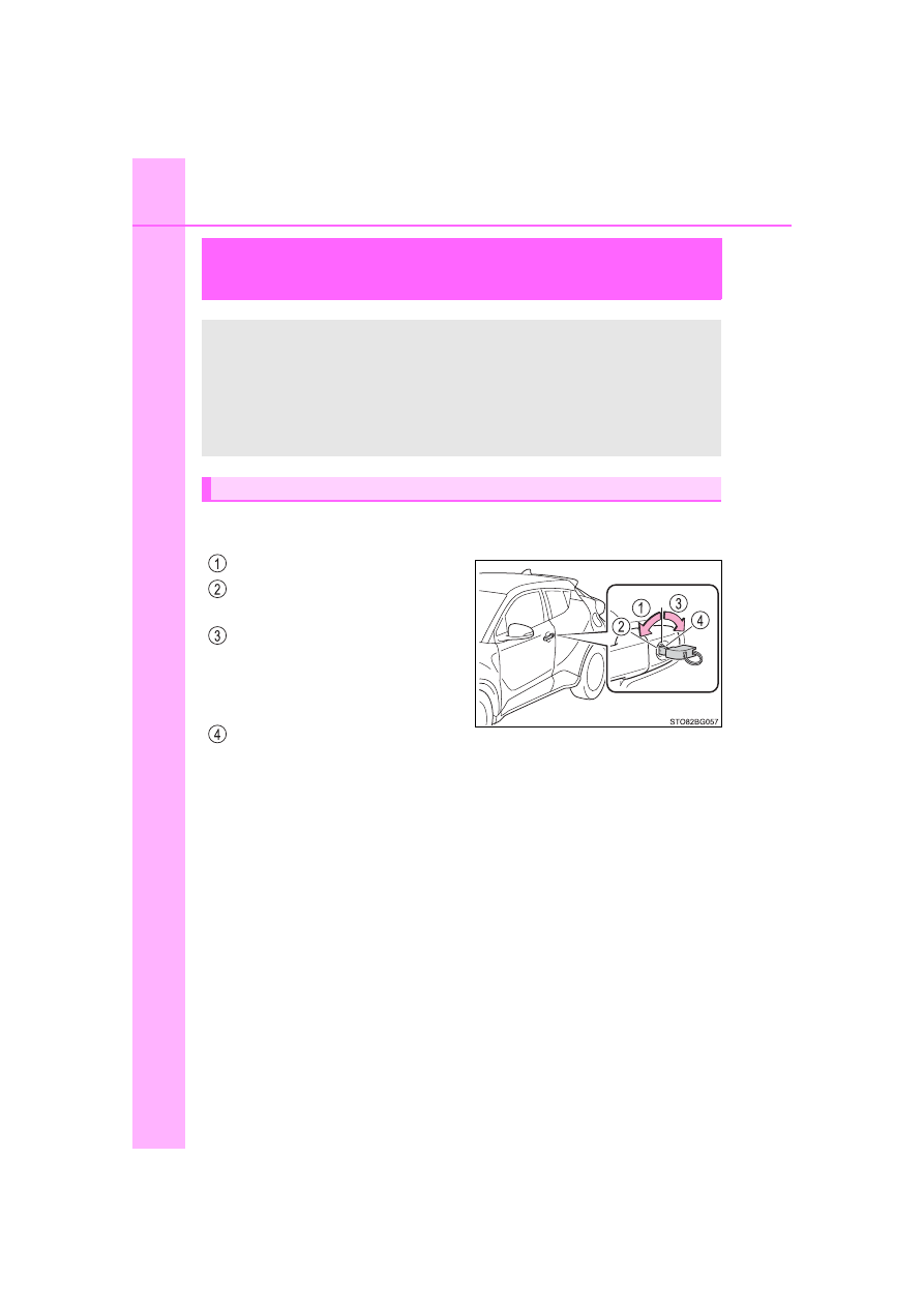
Use the mechanical key (

P. 114) in order to perform the following

operations:

Locks all the doors
Closes  the  windows  (turn  and
hold)

*

Unlocks the door

Turning  the  key  rearward  unlocks
the  driver’s  door.  Turning  the  key
once  again  within  3  seconds
unlocks the other doors.

Opens  the  windows  (turn  and
hold)

*

*

: These settings must be customized at your Toyota dealer. (

P. 506)

If  communication  between  the  electronic  key  and  vehicle  is
interrupted  (

P.  136)  or  the  electronic  key  cannot  be  used

because  the  battery  is  depleted,  the  smart  key  system  and
wireless  remote  control  cannot  be  used.  In  such  cases,  the
doors can be opened and the engine can be started by follow-
ing the procedure below.

Locking and unlocking the doors

-------------------------------------------------------------------------------------------------------------------------------------------------------------

463

7-2. Steps to take in an emergency

7

Wh
en tro

uble

 a

ris

es

C-HR_OM_USA_OM10684U

Ensure that the shift lever is in P and depress the brake pedal.
Touch  the  Toyota  emblem  side
of  the  electronic  key  to  the
engine switch.

When  the  electronic  key  is
detected, a buzzer sounds and the
engine switch will turn to IGNITION
ON mode.
When  the  smart  key  system  is
deactivated  in  customization  set-
ting,  the  engine  switch  will  turn  to
ACCESSORY mode.

Firmly  depress  the  brake  pedal  and  check  that 

  and  mes-

sages are shown on the multi-information display.
Press the engine switch.

In the event that the engine still cannot be started, contact your Toyota
dealer.

Starting the engine

1

2

3

4

-------------------------------------------------------------------------------------------------------------------------------------------------------------

464

7-2. Steps to take in an emergency

C-HR_OM_USA_OM10684U

Stopping the engine

Set the parking brake, shift the shift lever to P and press the engine switch as
you normally do when stopping the engine.

Replacing the key battery

As the above procedure is a temporary measure, it is recommended that the
electronic key battery be replaced immediately when the battery is depleted.
(

P. 397)

Changing engine switch modes

Release the brake pedal and press the engine switch in step 

 above. The

engine  does  not  start  and  modes  will  be  changed  each  time  the  switch  is
pressed. (

P. 184)

When the electronic key does not work properly

Make sure that the smart key system and push button start has not been
deactivated in the customization setting. If it is off, turn the function on. 
(Customizable features: 

P. 500)

Check if battery-saving mode is set. If it is set, cancel the function. 
(

P. 135)

WARNING

When using the mechanical key and operating the power windows

Operate the power window after checking to make sure that there is no pos-
sibility of any passenger having any of their body parts caught in the side
window. 
Also, do not allow children to operate the mechanical key. It is possible for
children and other passengers to get caught in the power window.

3

-------------------------------------------------------------------------------------------------------------------------------------------------------------

465

7-2. Steps to take in an emergency

C-HR_OM_USA_OM10684U

7

Wh
en tro

uble

 a

ris

es

If the vehicle battery is discharged

If you have a set of jumper (or booster) cables and a second vehicle
with a 12-volt battery, you can jump start your vehicle by following the
steps below.

Open the hood. (

P. 358)

Remove the engine cover.

Pull up the both ends of the cover
vertically.

The following procedures may be used to start the engine if the
vehicle’s battery is discharged.
You can also call your Toyota dealer or a qualified repair shop.

1

2

-------------------------------------------------------------------------------------------------------------------------------------------------------------

466

7-2. Steps to take in an emergency

C-HR_OM_USA_OM10684U

Connect the jumper cables according to the following procedure:

Connect a positive jumper cable clamp to the positive (+) battery
terminal on your vehicle.
Connect the clamp on the other end of the positive cable to the
positive (+) battery terminal on the second vehicle.
Connect a negative cable clamp to the negative (-) battery termi-
nal on the second vehicle.
Connect  the  clamp  at  the  other  end  of  the  negative  cable  to  a
solid, stationary, unpainted metallic point away from the battery
and any moving parts, as shown in the illustration.

Start the engine of the second vehicle. Increase the engine speed
slightly  and  maintain  at  that  level  for  approximately  5  minutes  to
recharge the battery of your vehicle.
Vehicles with a smart key system: Open and close any of the doors
of your vehicle with the engine switch off.

3

3

2

4

4

5

-------------------------------------------------------------------------------------------------------------------------------------------------------------

467

7-2. Steps to take in an emergency

7

Wh
en tro

uble

 a

ris

es

C-HR_OM_USA_OM10684U

Vehicles without a smart key system: 
Maintain  the  engine  speed  of  the  second  vehicle  and  turn  the
engine switch to the “ON” position, then start the vehicle’s engine.
Vehicles with a smart key system: 
Maintain  the  engine  speed  of  the  second  vehicle  and  turn  the
engine  switch  to  IGNITION  ON  mode,  then  start  the  vehicle’s
engine.
Once the vehicle’s engine has started, remove the jumper cables in
the exact reverse order from which they were connected. 
To  install  the  engine  cover,  conduct  the  removal  procedure  in
reverse.  After  installing,  check  that  the  fixed  pins  are  inserted
securely.

Once  the  engine  starts,  have  the  vehicle  inspected  at  your  Toyota
dealer as soon as possible.

Starting the engine when the battery is discharged 

The engine cannot be started by push-starting.

To prevent battery discharge

Turn off the headlights and the air conditioning system while the engine is
stopped.

Turn off any unnecessary electrical components when the vehicle is running
at a low speed for an extended period, such as in heavy traffic.

Charging the battery

The  electricity  stored  in  the  battery  will  discharge  gradually  even  when  the
vehicle is not in use, due to natural discharge and the draining effects of cer-
tain electrical appliances. If the vehicle is left for a long time, the battery may
discharge,  and  the  engine  may  be  unable  to  start.  (The  battery  recharges
automatically during driving.)

Precautions when the battery is discharged (vehicles with a smart key
system)

In some cases, it may not be possible to unlock the doors using the smart
entry  &  start  system  when  the  battery  is  discharged.  Use  the  wireless
remote control or the mechanical key to lock or unlock the doors.

The engine may not start on the first attempt after the battery has recharged
but will start normally after the second attempt. This is not a malfunction.

The engine switch mode is memorized by the vehicle. When the battery is
reconnected, the system will return to the mode it was in before the battery
was discharged. Before disconnecting the battery, turn the engine switch off. 
If you are unsure what mode the engine switch was in before the battery dis-
charged, be especially careful when reconnecting the battery.

6

7

8

-------------------------------------------------------------------------------------------------------------------------------------------------------------

468

7-2. Steps to take in an emergency

C-HR_OM_USA_OM10684U

When replacing the battery

Use a battery that conforms to European regulations.

Use a battery that the case size is same as the previous one, 20 hour rate
capacity (20HR) is equivalent or greater, and performance rating (CCA) is
equivalent or greater. 
Check the label on top of the battery for the battery size and specifications
(ex. LN2, 60Ah, 345A).
• If the sizes differ, the battery cannot be properly secured.
• If the 20 hour rate capacity is low, even if the time period where the vehi-

cle is not used is a short time, the battery may discharge and the engine
may not be able to start.

For details, consult your Toyota dealer.

WARNING

Avoiding battery fires or explosions

Observe the following precautions to prevent accidentally igniting the flam-
mable gas that may be emitted from the battery:

Make sure each jumper cable is connected to the correct terminal and that
it is not unintentionally in contact with any other than the intended terminal.

Do not allow the other end of the jumper cable connected to the “+” termi-
nal to come into contact with any other parts or metal surfaces in the area,
such as brackets or unpainted metal.

Do not allow the + and - clamps of the jumper cables to come into contact
with each other.

Do  not smoke,  use matches, cigarette lighters  or  allow  open flame near
the battery.

Battery precautions

The  battery  contains  poisonous  and  corrosive  acidic  electrolyte,  while
related parts contain lead and lead compounds. Observe the following pre-
cautions when handling the battery:

When working with the battery, always wear safety glasses and take care
not to allow any battery fluids (acid) to come into contact with skin, clothing
or the vehicle body.

Do not lean over the battery.

In  the  event  that  battery  fluid  comes  into  contact  with  the  skin  or  eyes,
immediately wash the affected area with water and seek medical attention.
Place a wet sponge or cloth over the affected area until medical attention
can be received.

Always wash your hands after handling the battery support, terminals, and
other battery-related parts.

Do not allow children near the battery.

-------------------------------------------------------------------------------------------------------------------------------------------------------------

469

7-2. Steps to take in an emergency

7

Wh
en tro

uble

 a

ris

es

C-HR_OM_USA_OM10684U

NOTICE

When handling jumper cables

When connecting the jumper cables, ensure that they do not become entan-
gled in the cooling fan or engine drive belt.

-------------------------------------------------------------------------------------------------------------------------------------------------------------

470

7-2. Steps to take in an emergency

C-HR_OM_USA_OM10684U

If your vehicle overheats

The  needle  of  the  engine  coolant  temperature  gauge  (

P.  96)

enters the red zone or a loss of engine power is experienced (for
example, the vehicle speed does not increase).

Steam comes out from under the hood.

Stop the vehicle in a safe place and turn off the air conditioning sys-
tem, and then stop the engine.
If you see steam: 
Carefully lift the hood after the steam subsides.
If you do not see steam:
Carefully lift the hood.
After  the  engine  has  cooled
down  sufficiently,  inspect  the
hoses and radiator core (radia-
tor) for any leaks.

Radiator
Cooling fan

If  a  large  amount  of  coolant
leaks,  immediately  contact  your
Toyota dealer.

The following may indicate that your vehicle is overheating.

Correction procedures

1

2

3

-------------------------------------------------------------------------------------------------------------------------------------------------------------

471

7-2. Steps to take in an emergency

7

Wh
en tro

uble

 a

ris

es

C-HR_OM_USA_OM10684U

The coolant level is satisfactory
if  it  is  between  the  “FULL”  and
“LOW” lines on the reservoir.

Reservoir
“FULL” line
“LOW” line

Add coolant if necessary.

Water  can  be  used  in  an  emer-
gency if coolant is unavailable.

Start the engine and turn the air conditioning system on to check
that the radiator cooling fan operates and to check for coolant leaks
from the radiator or hoses.

The fan operates when the air conditioning system is turned on immedi-
ately after a cold start. Confirm that the fan is operating by checking the fan
sound and air flow. If it is difficult to check these, turn the air conditioning
system on and off repeatedly.
(The fan may not operate in freezing temperatures.)

If the fan is not operating: 
Stop the engine immediately and contact your Toyota dealer.
If the fan is operating: 
Have the vehicle inspected at the nearest Toyota dealer.

4

5

6

7

-------------------------------------------------------------------------------------------------------------------------------------------------------------

472

7-2. Steps to take in an emergency

C-HR_OM_USA_OM10684U

WARNING

When inspecting under the hood of your vehicle

Observe the following precautions. 
Failure to do so may result in serious injury such as burns.

If steam is seen coming from under the hood, do not open the hood until
the steam has subsided. The engine compartment may be very hot.

Keep hands and clothing (especially a tie, a scarf or a muffler) away from
the fan and belts. Failure to do so may cause the hands or clothing to be
caught, resulting in serious injury.

Do not loosen the coolant reservoir cap while the engine and radiator are
hot.
High temperature steam or coolant could spray out.

NOTICE

When adding coolant

Add  coolant  slowly  after  the  engine  has  cooled  down  sufficiently. Adding
cool coolant to a hot engine too quickly can cause damage to the engine.

To prevent damage to the cooling system

Observe the following precautions:

Avoid contaminating the coolant with foreign matter (such as sand or dust
etc.).

Do not use any coolant additives.

-------------------------------------------------------------------------------------------------------------------------------------------------------------

473

7-2. Steps to take in an emergency

C-HR_OM_USA_OM10684U

7

Wh
en tro

uble

 a

ris

es

If the vehicle becomes stuck

Stop the engine. Shift the shift lever to P, and set the parking brake.
Remove the mud, snow or sand from around the front wheels.
Place wood, stones or some other material under the front wheels
to help provide traction.
Restart the engine.
Shift the shift lever to D or R and release the parking brake. Then,
while exercising caution, depress the accelerator pedal.

When it is difficult to free the vehicle

Carry out the following procedures if the tires spin or the vehicle
becomes stuck in mud, dirt or snow:

Press 

 to turn off TRAC.

A  message  will  be  shown  on  the  multi-
information display.

1

2

3

4

5

-------------------------------------------------------------------------------------------------------------------------------------------------------------

474

7-2. Steps to take in an emergency

C-HR_OM_USA_OM10684U

WARNING

When attempting to free a stuck vehicle

If you choose to push the vehicle back and forth to free it, make sure the
surrounding area is clear to avoid striking other vehicles, objects or people.
The vehicle may also lunge forward or lunge back suddenly as it becomes
free. Use extreme caution.

When shifting the shift lever

Be careful not to shift the shift lever with the accelerator pedal depressed.
This  may  lead  to  unexpected  rapid  acceleration  of  the  vehicle  that  may
cause an accident resulting in death or serious injury.

NOTICE

To avoid damaging the transmission and other components

Avoid  spinning  the  front  wheels  and  depressing  the  accelerator  pedal
more than necessary.

If  the  vehicle  remains  stuck even  after  these procedures  are  performed,
the vehicle may require towing to be freed.

-------------------------------------------------------------------------------------------------------------------------------------------------------------

475

8

Vehicle specifications

C-HR_OM_USA_OM10684U

8-1. Specifications

Maintenance data 

(fuel, oil level, etc.).......... 476

Fuel information ................ 484
Tire information ................. 487

8-2. Customization

Customizable features ...... 500

8-3. Items to initialize

Items to initialize ............... 512

-------------------------------------------------------------------------------------------------------------------------------------------------------------

476

8-1. Specifications

C-HR_OM_USA_OM10684U

Maintenance data (fuel, oil level, etc.)

*

1

: Unladen vehicles

*

2

: Vehicles with 215/60R17 tires

*

3

: Vehicles with 225/50R18 tires

Vehicle identification number

The  vehicle  identification  number  (VIN)  is  the  legal  identifier  for
your  vehicle.  This  is  the  primary  identification  number  for  your
Toyota. It is used in registering the ownership of your vehicle.
This number is also stamped on
the  top  left  of  the  instrument
panel.

Dimensions and weights

Overall length

172.6 in. (4385 mm)

Overall width

70.7 in. (1795 mm)

Overall height

*

1

61.2 in. (1555 mm)

Wheelbase

103.9 in. (2640 mm)

Tread

Front

61.0 in. (1550 mm)

*

2

60.6 in. (1540 mm)

*

3

Rear

61.4 in. (1560 mm)

*

2

61.0 in. (1550 mm)

*

3

Vehicle capacity weight

(occupants + luggage)

825 lb. (375 kg)

Seating capacity

Seating capacity

5 (Front 2, Rear 3)

Vehicle identification

-------------------------------------------------------------------------------------------------------------------------------------------------------------

477

8-1. Specifications

8

Vehi

cl

e specificatio

ns

C-HR_OM_USA_OM10684U

This  number  is  stamped  under
the right-hand front seat.

This number is also on the Cer-
tification Label.

Engine number

The engine number is stamped
on the engine block as shown.

-------------------------------------------------------------------------------------------------------------------------------------------------------------

478

8-1. Specifications

C-HR_OM_USA_OM10684U

*

: The engine oil capacity is a reference quantity to be used when changing

the engine oil. Warm up and turn off the engine, wait more than 5 minutes,
and check the oil level on the dipstick.

Engine

Model

3ZR-FAE

Type

4-cylinder in line, 4-cycle, gasoline

Bore and stroke

3.17 

 3.84 in. (80.5 

 97.6 mm)

Displacement

121.3 cu.in. (1987 cm

3

)

Valve clearance (engine
cold)

Automatic adjustment

Drive belt tension

Automatic adjustment

Fuel

Fuel type

Unleaded gasoline only

Octane rating

87 (Research Octane Number 91) or higher

Fuel tank capacity
(Reference)

13.2 gal. (50 L, 11.0 Imp.gal.)

Lubrication system

Oil capacity
(Drain and refill 


reference

*

)

With filter
Without filter

4.4 qt. (4.2 L, 3.7 Imp.qt.)
4.1 qt. (3.9 L, 3.4 Imp.qt.)

-------------------------------------------------------------------------------------------------------------------------------------------------------------

479

8-1. Specifications

8

Vehi

cl

e specificatio

ns

C-HR_OM_USA_OM10684U

Engine oil selection

“Toyota  Genuine  Motor  Oil”  is  used  in  your  Toyota  vehicle.  Use
Toyota approved “Toyota Genuine Motor Oil” or equivalent to satisfy
the following grade and viscosity.
Oil grade: ILSAC GF-5 multigrade engine oil
Recommended viscosity: SAE 0W-20

SAE  0W-20  is  the  best  choice  for
good fuel economy and good start-
ing in cold weather.
If SAE 0W-20 is not available, SAE
5W-20 oil may be used. However, it
must be replaced with SAE 0W-20
at the next oil change.

Oil viscosity (0W-20 is explained here as an example):

• The 0W in 0W-20 indicates the characteristic of the oil which allows cold

startability. Oils with a lower value before the W allow for easier starting of
the engine in cold weather.

• The 20 in 0W-20 indicates the viscosity characteristic of the oil when the

oil is at high temperature. An oil with a higher viscosity (one with a higher
value) may be better suited if the vehicle is operated at high speeds, or
under extreme load conditions.

How to read oil container label:
The  International  Lubricant
Specification Advisory  Commit-
tee  (ILSAC)  Certification  Mark
is added to some oil containers
to  help  you  select  the  oil  you
should use.

Outside temperature

-------------------------------------------------------------------------------------------------------------------------------------------------------------

480

8-1. Specifications

C-HR_OM_USA_OM10684U

Cooling system 

Capacity

6.1 qt. (5.7 L, 5.1 Imp.qt.)

Coolant type

Use either of the following.

• “Toyota Super Long Life Coolant” 
• Similar  high-quality  ethylene  glycol-based  non-sili-

cate,  non-amine,  non-nitrite,  and  non-borate  cool-
ant with long-life hybrid organic acid technology

Do not use plain water alone.

Ignition system

Spark plug

Make

DENSO SC16HR11

Gap

0.043 in. (1.1 mm)

NOTICE

Iridium-tipped spark plugs

Use only iridium-tipped spark plugs. Do not adjust spark plug gap.

Electrical system

Battery

Specific volt-
age reading at 
68

F (20

C):

12.3 V or higher
(Turn the engine switch to off and turn on the high beam
headlights for 30 seconds.) 
If the voltage is lower than the standard value, charge
the battery.

Specific grav-
ity reading at 
68

F (20

C):

1.25 or higher
If the specific gravity is lower than the standard value,
charge the battery.

Charging rates

Quick charge
Slow charge

15 A max.
5 A max.

-------------------------------------------------------------------------------------------------------------------------------------------------------------

481

8-1. Specifications

8

Vehi

cl

e specificatio

ns

C-HR_OM_USA_OM10684U

*

: The fluid capacity is a reference quantity.

If replacement is necessary, contact your Toyota dealer.

*

: Minimum pedal clearance when depressed with a force of 30.6 kgf (300 N,

67.4 lbf) while the engine is running

Continuously variable transmission

Fluid capacity

*

7.6 qt. (7.2 L, 6.3 Imp.qt.)

Fluid type

Toyota Genuine CVT Fluid FE

NOTICE

Continuously variable transmission fluid type

Using  continuously  variable  transmission  fluid  other  than  the  above  type
may  cause abnormal noise or  vibration,  or  damage the  continuously vari-
able transmission of your vehicle.

Brakes

Pedal clearance

*

5.0 in. (127 mm)

Pedal free play

0.04 

 0.20 in. (1 

 5 mm)

Brake pad wear limit

0.04 in. (1.0 mm)

Fluid type

SAE J1703 or FMVSS No.116 DOT 3; 
SAE J1704 or FMVSS No.116 DOT 4

Steering

Free play

Less than 1.2 in. (30 mm)

-------------------------------------------------------------------------------------------------------------------------------------------------------------

482

8-1. Specifications

C-HR_OM_USA_OM10684U

17-inch tires

18-inch tires

Compact spare tire

Tires and wheels

Tire size

215/60R17 96H

Tire inflation pressure

(Recommended  cold  tire

inflation pressure)

Front tires:

33 psi (230 kPa, 2.3 kgf/cm

2

 or bar)

Rear tires: 

33 psi (230 kPa, 2.3 kgf/cm

2

 or bar)

Wheel size

17 

 6 1/2J

Wheel nut torque

76 ft·lbf (103 N·m, 10.5 kgf·m)

Tire size

225/50R18 95V

Tire inflation pressure

(Recommended  cold  tire

inflation pressure)

Front tires: 

33 psi (230 kPa, 2.3 kgf/cm

2

 or bar)

Rear tires: 

33 psi (230 kPa, 2.3 kgf/cm

2

 or bar)

Wheel size

18 

 7 J

Wheel nut torque

76 ft·lbf (103 N·m, 10.5 kgf·m)

Tire size

T145/90D16 106M, T145/70D18 107M

Tire inflation pressure

(Recommended  cold  tire

inflation pressure)

60 psi (420 kPa, 4.2 kgf/cm

2

 or bar)

Wheel size

16 

 4 T, 18 

 4 T

Wheel nut torque

76 ft·lbf (103 N·m, 10.5 kgf·m)

-------------------------------------------------------------------------------------------------------------------------------------------------------------

483

8-1. Specifications

8

Vehi

cl

e specificatio

ns

C-HR_OM_USA_OM10684U

Light bulbs

Light bulbs

Bulb No.

W

Type

Exterior

Front side marker lights
(bulb type)

5

A

Front  turn  signal  lights
(bulb type)

21

B

Side turn signal lights 

5

B

Rear side marker lights

5

A

Rear turn signal lights

21

B

Back-up lights

921

16

A

License plate lights

5

A

Interior

Vanity lights

*

8

A

Front  interior  lights/
front personal lights

5

A

Rear interior light

8

C

Luggage  compartment
light

5

A

A: Wedge base bulbs (clear)

C: Double end bulbs

*

: If equipped

B: Wedge base bulbs (amber)

-------------------------------------------------------------------------------------------------------------------------------------------------------------

484

8-1. Specifications

C-HR_OM_USA_OM10684U

Fuel information

Gasoline quality

In very few cases, driveability problems may be caused by the brand of gaso-
line you are using. If driveability problems persist, try changing the brand of
gasoline. If this does not correct the problem, consult your Toyota dealer.

Recommendation of the use of gasoline containing detergent additives

Toyota recommends the use of gasoline that contains detergent additives to
avoid the build-up of engine deposits.

All  gasoline  sold  in  the  U.S.A.  contains  minimum  detergent  additives  to
clean and/or keep clean intake systems, per EPA’s lowest additives concen-
tration program.

Toyota  strongly  recommends  the  use  of Top Tier  Detergent  Gasoline.  For
more  information  on Top Tier  Detergent  Gasoline  and  a  list  of  marketers,
please go to the official website www.toptiergas.com.

Recommendation of the use of low emissions gasoline

Gasolines  containing  oxygenates  such  as  ethers  and  ethanol,  as  well  as
reformulated gasolines, are available in some cities. These fuels are typically
acceptable for use, providing they meet other fuel requirements.
Toyota  recommends  these  fuels,  since  the  formulations  allow  for  reduced
vehicle emissions.

You must only use unleaded gasoline.
Select octane rating 87 (Research Octane Number 91) or higher.
Use  of  unleaded  gasoline  with  an  octane  rating  lower  than  87
may result in engine knocking. Persistent knocking can lead to
engine damage.

At minimum, the gasoline you use should meet the specifications of
ASTM D4814 in the U.S.A.

-------------------------------------------------------------------------------------------------------------------------------------------------------------

485

8-1. Specifications

8

Vehi

cl

e specificatio

ns

C-HR_OM_USA_OM10684U

Non-recommendation of the use of blended gasoline

If you use gasohol in your vehicle, be sure that it has an octane rating no
lower than 87.

Toyota does not recommend the use of gasoline containing methanol.

Non-recommendation of the use of gasoline containing MMT

Some gasoline contains an octane enhancing additive called MMT (Methylcy-
clopentadienyl Manganese Tricarbonyl).
Toyota  does  not  recommend  the  use  of  gasoline  that  contains  MMT.  If  fuel
containing  MMT  is  used,  your  emission  control  system  may  be  adversely
affected.
The malfunction indicator lamp on the instrument cluster may come on. If this
happens, contact your Toyota dealer for service.

If your engine knocks

Consult your Toyota dealer.

You may occasionally notice light knocking for a short time while accelerat-
ing or driving uphill. This is normal and there is no need for concern.

Use only gasoline containing up to 15%
ethanol.
DO  NOT  use  any  flex-fuel  or  gasoline
that could contain more than 15% etha-
nol,  including  from  any  pump  labeled
E30,  E50,  E85  (which  are  only  some
examples  of  fuel  containing  more  than
15% ethanol).

DO NOT use gasoline contain-
ing more than 15% ethanol.

(30% ethanol)

(50% ethanol)

(85% ethanol)

-------------------------------------------------------------------------------------------------------------------------------------------------------------

486

8-1. Specifications

C-HR_OM_USA_OM10684U

NOTICE

Notice on fuel quality

Do not use improper fuels. If improper fuels are used, the engine will be
damaged.

Do not use leaded gasoline.
Leaded gasoline can cause damage to your vehicle’s three-way catalytic
converters causing the emission control system to malfunction.

Do not use gasohol other than the type previously stated.
Other  gasohol  may  cause  fuel  system  damage  or  vehicle  performance
problems.

Using unleaded gasoline with an octane number or rating lower than the
level previously stated will cause persistent heavy knocking.
At worst, this will lead to engine damage.

Fuel-related poor driveability

If poor driveability (poor hot starting, vaporization, engine knocking, etc.) is
encountered after using a different type of fuel, discontinue the use of that
type of fuel.

When refueling with gasohol

Take care not to spill gasohol. It can damage your vehicle’s paint.

-------------------------------------------------------------------------------------------------------------------------------------------------------------

487

8-1. Specifications

C-HR_OM_USA_OM10684U

8

Vehi

cl

e specificatio

ns

Tire information

Full-size tire

Compact spare tire

Typical tire symbols

-------------------------------------------------------------------------------------------------------------------------------------------------------------

488

8-1. Specifications

C-HR_OM_USA_OM10684U

Tire size (

P. 490)

DOT and Tire Identification Number (TIN) (

P. 489)

Uniform tire quality grading

For details, see “Uniform Tire Quality Grading” that follows.

Location of treadwear indicators (

P. 376)

Tire ply composition and materials

Plies are layers of rubber-coated parallel cords. Cords are the strands

which form the plies in a tire.

Radial tires or bias-ply tires

A radial tire has “RADIAL” on the sidewall. A tire not marked “RADIAL”

is a bias-ply tire.

TUBELESS or TUBE TYPE

A tubeless tire does not have a tube and air is directly put into the tire.

A tube type tire has a tube inside the tire and the tube maintains the air

pressure.

Load limit at maximum cold tire inflation pressure (

P. 380)

Maximum cold tire inflation pressure (

P. 482)

This means the pressure to which a tire may be inflated.

Summer tires or all season tires (

P. 380)

An all season tire has “M+S” on the sidewall. A tire not marked “M+S”

is a summer tire.

“TEMPORARY USE ONLY”

A  compact  spare  tire  is  identified  by  the  phrase  “TEMPORARY  USE

ONLY”  molded  on  its  sidewall.  This  tire  is  designed  for  temporary

emergency use only.

-------------------------------------------------------------------------------------------------------------------------------------------------------------

489

8-1. Specifications

8

Vehi

cl

e specificatio

ns

C-HR_OM_USA_OM10684U

DOT symbol

*

Tire Identification Number (TIN)
Tire manufacturer’s identification mark
Tire size code
Manufacturer’s optional tire type code (3 or 4 letters)
Manufacturing week
Manufacturing year
Manufacturer’s code

*

: The DOT symbol certifies that the tire conforms to applicable Federal

Motor Vehicle Safety Standards.

Typical DOT and Tire Identification Number (TIN)

Type A

Type B

-------------------------------------------------------------------------------------------------------------------------------------------------------------

490

8-1. Specifications

C-HR_OM_USA_OM10684U

Typical tire size information

The illustration indicates typical
tire size.

Tire use (P = Passenger car, 
T = Temporary use)
Section width (millimeters)
Aspect ratio 
(tire height to section width)
Tire construction code 
(R = Radial, D = Diagonal)
Wheel diameter (inches)
Load index 
(2 digits or 3 digits)
Speed symbol 
(alphabet with one letter)

Tire dimensions

Section width
Tire height
Wheel diameter

Tire size

-------------------------------------------------------------------------------------------------------------------------------------------------------------

491

8-1. Specifications

8

Vehi

cl

e specificatio

ns

C-HR_OM_USA_OM10684U

Bead
Sidewall
Shoulder
Tread
Belt
Inner liner
Reinforcing rubber
Carcass
Rim lines
Bead wires
Chafer

Tire section names

-------------------------------------------------------------------------------------------------------------------------------------------------------------

492

8-1. Specifications

C-HR_OM_USA_OM10684U

This  information  has  been  prepared  in  accordance  with  regulations
issued  by  the  National  Highway  Traffic  Safety Administration  of  the
U.S. Department of Transportation.
It  provides  the  purchasers  and/or  prospective  purchasers  of  Toyota
vehicles with information on uniform tire quality grading.

Your Toyota  dealer  will  help  answer  any  questions  you  may  have  as

you read this information.

DOT quality grades

All passenger vehicle tires must conform to Federal Safety Require-
ments  in  addition  to  these  grades.  Quality  grades  can  be  found
where applicable on the tire sidewall between tread shoulder and
maximum section width.

For example: Treadwear 200 Traction AA Temperature A

Treadwear

The  treadwear  grade  is  a  comparative  rating  based  on  the  wear
rate of the tire when tested under controlled conditions on a speci-
fied government test course.

For example, a tire graded 150 would wear one and a half (1 - 1/2)

times as well on the government course as a tire graded 100.

The  relative  performance  of  tires  depends  upon  the  actual  condi-

tions of their use. Performance may differ significantly from the norm

due to variations in driving habits, service practices and differences

in road characteristics and climate.

Traction AA, A, B, C

The  traction  grades,  from  highest  to  lowest,  are AA, A,  B  and  C,
and  they  represent  the  tire’s  ability  to  stop  on  wet  pavement  as
measured under controlled conditions on specified government test
surfaces of asphalt and concrete.

A tire marked C may have poor traction performance.
Warning: The traction grade assigned to this tire is based on braking

(straight ahead) traction tests and does not include cornering (turn-

ing) traction.

Uniform Tire Quality Grading

-------------------------------------------------------------------------------------------------------------------------------------------------------------

493

8-1. Specifications

8

Vehi

cl

e specificatio

ns

C-HR_OM_USA_OM10684U

Temperature A, B, C

The temperature grades are A (the highest), B, and C, representing
the tire’s resistance to the generation of heat and its ability to dissi-
pate  heat  when  tested  under  controlled  conditions  on  a  specified
indoor laboratory test wheel.

Sustained  high  temperature  can  cause  the  material  of  the  tire  to

degenerate and reduce tire life, and excessive temperature can lead

to sudden tire failure.
Grade C corresponds to a level of performance which all passenger

car  tires  must  meet  under  the  Federal  Motor  Vehicle  Safety  Stan-

dard No. 109.
Grades B and A represent higher levels of performance on the labo-

ratory test wheel than the minimum required by law.
Warning: The temperature grades of a tire assume that it is properly

inflated and not overloaded.

Excessive speed, underinflation, or excessive loading, either sepa-

rately  or  in  combination,  can  cause  heat  buildup  and  possible  tire

failure.

-------------------------------------------------------------------------------------------------------------------------------------------------------------

494

8-1. Specifications

C-HR_OM_USA_OM10684U

Glossary of tire terminology

Tire related term

Meaning

Cold tire inflation pres-

sure

Tire  pressure  when  the  vehicle  has  been

parked  for  three  hours  or  more,  or  has  not

been driven more than 1 mile or 1.5 km under

that condition

Maximum 

inflation

pressure

The maximum cold inflated pressure to which

a tire may be inflated, shown on the sidewall

of the tire

Recommended  infla-

tion pressure

Cold tire inflation pressure recommended by a

manufacturer

Accessory weight

The combined weight (in excess of those stan-

dard  items  which  may  be  replaced)  of  auto-

matic  transmission,  power  steering,  power

brakes,  power  windows,  power  seats,  radio

and heater, to the extent that these items are

available  as  factory-installed  equipment

(whether installed or not)

Curb weight

The  weight  of  a  motor  vehicle  with  standard

equipment, including the maximum capacity of

fuel,  oil  and  coolant,  and  if  so  equipped,  air

conditioning  and  additional  weight  optional

engine

Maximum loaded vehi-

cle weight

The sum of:

(a) Curb weight

(b) Accessory weight

(c) Vehicle capacity weight

(d) Production options weight

Normal 

occupant

weight

150 lb. (68 kg) times the number of occupants

specified  in  the  second  column  of  Table  1

*

that follows

Occupant distribution

Distribution of occupants in a vehicle as speci-

fied in the third column of Table 1

*

 below

-------------------------------------------------------------------------------------------------------------------------------------------------------------

495

8-1. Specifications

8

Vehi

cl

e specificatio

ns

C-HR_OM_USA_OM10684U

Production 

options

weight

The combined weight of installed regular pro-

duction options weighing over 5 lb. (2.3 kg) in

excess  of  the  standard  items  which  they

replace,  not  previously  considered  in  curb

weight  or  accessory  weight,  including  heavy

duty  brakes,  ride  levelers,  roof  rack,  heavy

duty battery, and special trim

Rim

A  metal  support  for  a  tire  or  a  tire  and  tube

assembly  upon  which  the  tire  beads  are

seated

Rim diameter

(Wheel diameter)

Nominal diameter of the bead seat

Rim size designation

Rim diameter and width

Rim type designation

The industry manufacturer’s designation for a

rim by style or code

Rim width

Nominal distance between rim flanges

Vehicle 

capacity

weight 

(Total 

load

capacity)

The rated cargo and luggage load plus 150 lb.

(68 kg) times the vehicle’s designated seating

capacity

Vehicle maximum load

on the tire

The  load  on  an  individual  tire  that  is  deter-

mined by distributing to each axle its share of

the  maximum  loaded  vehicle  weight,  and

dividing by two

Vehicle normal load on

the tire

The  load  on  an  individual  tire  that  is  deter-

mined by distributing to each axle its share of

curb  weight,  accessory  weight,  and  normal

occupant  weight  (distributed  in  accordance

with Table 1

*

 below), and dividing by two

Weather side

The surface area of the rim not covered by the

inflated tire

Bead

The part of the tire that is made of steel wires,

wrapped or reinforced by ply cords and that is

shaped to fit the rim

Bead separation

A  breakdown  of  the  bond  between  compo-

nents in the bead

Tire related term

Meaning

-------------------------------------------------------------------------------------------------------------------------------------------------------------

496

8-1. Specifications

C-HR_OM_USA_OM10684U

Bias ply tire

A  pneumatic  tire  in  which  the  ply  cords  that

extend  to  the  beads  are  laid  at  alternate

angles  substantially  less  than  90  degrees  to

the centerline of the tread

Carcass

The  tire  structure,  except  tread  and  sidewall

rubber which, when inflated, bears the load

Chunking

The  breaking  away  of  pieces  of  the  tread  or

sidewall

Cord

The strands forming the plies in the tire

Cord separation

The  parting  of  cords  from  adjacent  rubber

compounds

Cracking

Any parting within the tread, sidewall, or inner-

liner of the tire extending to cord material

CT

A  pneumatic  tire  with  an  inverted  flange  tire

and  rim  system  in  which  the  rim  is  designed

with  rim  flanges  pointed  radially  inward  and

the  tire  is  designed  to  fit  on  the  underside  of

the  rim  in  a  manner  that  encloses  the  rim

flanges inside the air cavity of the tire

Extra load tire

A tire designed to operate at higher loads and

at  higher  inflation  pressures  than  the  corre-

sponding standard tire

Groove

The space between two adjacent tread ribs

Innerliner

The  layer(s)  forming  the  inside  surface  of  a

tubeless tire that contains the inflating medium

within the tire

Innerliner separation

The parting of the innerliner from cord material

in the carcass

Intended 

outboard

sidewall

(a) The  sidewall  that  contains  a  whitewall,

bears  white  lettering,  or  bears  manufac-

turer,  brand,  and/or  model  name  molding

that  is  higher  or  deeper  than  the  same

molding on the other sidewall of the tire, or

(b) The  outward  facing  sidewall  of  an  asym-

metrical tire that has a particular side that

must always face outward when mounted

on a vehicle

Tire related term

Meaning

-------------------------------------------------------------------------------------------------------------------------------------------------------------

497

8-1. Specifications

8

Vehi

cl

e specificatio

ns

C-HR_OM_USA_OM10684U

Light truck (LT) tire

A  tire  designated  by  its  manufacturer  as  pri-

marily  intended  for  use  on  lightweight  trucks

or multipurpose passenger vehicles

Load rating

The maximum load that a tire is rated to carry

for a given inflation pressure

Maximum load rating

The load rating for a tire at the maximum per-

missible inflation pressure for that tire

Maximum  permissible

inflation pressure

The maximum cold inflation pressure to which

a tire may be inflated

Measuring rim

The  rim  on  which  a  tire  is  fitted  for  physical

dimension requirements

Open splice

Any parting at any junction of tread, sidewall,

or innerliner that extends to cord material

Outer diameter

The overall diameter of an inflated new tire

Overall width

The  linear  distance  between  the  exteriors  of

the sidewalls of an inflated tire, including ele-

vations due to labeling, decorations, or protec-

tive bands or ribs

Passenger car tire

A  tire  intended  for  use  on  passenger  cars,

multipurpose passenger vehicles, and trucks,

that  have  a  gross  vehicle  weight  rating

(GVWR) of 10,000 lb. or less.

Ply

A layer of rubber-coated parallel cords

Ply separation

A  parting  of  rubber  compound  between  adja-

cent plies

Pneumatic tire

A  mechanical  device  made  of  rubber,  chemi-

cals, fabric and steel or other materials, that,

when  mounted  on  an  automotive  wheel,  pro-

vides the traction and contains the gas or fluid

that sustains the load

Radial ply tire

A  pneumatic  tire  in  which  the  ply  cords  that

extend to the beads are laid at substantially 90

degrees to the centerline of the tread

Reinforced tire 

A tire designed to operate at higher loads and

at  higher  inflation  pressures  than  the  corre-

sponding standard tire

Tire related term

Meaning

-------------------------------------------------------------------------------------------------------------------------------------------------------------

498

8-1. Specifications

C-HR_OM_USA_OM10684U

*

: Table 1 

 Occupant loading and distribution for vehicle normal load for

various designated seating capacities

Section width

The  linear  distance  between  the  exteriors  of

the sidewalls of an inflated tire, excluding ele-

vations due to labeling, decoration, or protec-

tive bands

Sidewall

That  portion  of  a  tire  between  the  tread  and

bead

Sidewall separation

The parting of the rubber compound from the

cord material in the sidewall

Snow tire

A tire that attains a traction index equal to or

greater  than  110,  compared  to  the  ASTM

E-1136  Standard  Reference  Test  Tire,  when

using  the  snow  traction  test  as  described  in

ASTM  F-1805-00,  Standard  Test  Method  for

Single  Wheel  Driving  Traction  in  a  Straight

Line on Snow-and Ice-Covered Surfaces, and

which is marked with an Alpine Symbol (

)

on at least one sidewall

Test rim

The rim on which a tire is fitted for testing, and

may  be  any  rim  listed  as  appropriate  for  use

with that tire

Tread

That  portion  of  a  tire  that  comes  into  contact

with the road

Tread rib

A  tread  section  running  circumferentially

around a tire

Tread separation

Pulling away of the tread from the tire carcass

Treadwear  indicators

(TWI)

The  projections  within  the  principal  grooves

designed  to  give  a  visual  indication  of  the

degrees of wear of the tread

Wheel-holding fixture

The  fixture  used  to  hold  the  wheel  and  tire

assembly securely during testing

Tire related term

Meaning

-------------------------------------------------------------------------------------------------------------------------------------------------------------

499

8-1. Specifications

8

Vehi

cl

e specificatio

ns

C-HR_OM_USA_OM10684U

Designated seating 

capacity, Number of 

occupants

Vehicle normal load, 

Number of occupants

Occupant distribution 

in a normally loaded 

vehicle

2 through 4

2

2 in front

5 through 10

3

2 in front, 1 in second 

seat

11 through 15

5

2 in front, 1 in second 

seat, 1 in third seat, 1 

in fourth seat

16 through 20

7

2 in front, 2 in second 

seat, 2 in third seat, 1 

in fourth seat

-------------------------------------------------------------------------------------------------------------------------------------------------------------

500

8-2. Customization

C-HR_OM_USA_OM10684U

Customizable features

Changing using the multi-information display

Press “

” or “

” of the meter control switches, select 

.

Press  “

”  or  “

”  of  the  meter  control  switches,  select  “Meter  Set-

tings”, and then press 

.

Press “

” or “

” of the meter control switches, select the item, and

then press 

.

Press  “

”  or  “

”  of  the  meter  control  switches,  select  the  desired

setting, and then press 

.

To go back to the previous screen or exit the customize mode, press

.

Your vehicle includes a variety of electronic features that can be
personalized to suit your preferences. The settings of these fea-
tures can be changed using the multi-information display or at
your Toyota dealer.

Customizing vehicle features

1

2

3

4

-------------------------------------------------------------------------------------------------------------------------------------------------------------

501

8-2. Customization

8

Vehi

cl

e specificatio

ns

C-HR_OM_USA_OM10684U

Changing on the audio system screen

Press the “MENU” button.

Select “Setup” on the menu screen and select “Vehicle”.

Select “Vehicle Customization”.

Various setting can be changed. Refer to the list of settings that can
be changed for details.

Some function settings are changed simultaneously with other func-
tions when customized. Contact your Toyota dealer for further details.

Settings that can be changed using the multi-information display
Settings that can be changed on the audio system screen
Settings that can be changed by your Toyota dealer

Definition of symbols: O = Available, — = Not available

Customizable features

1

2

3

-------------------------------------------------------------------------------------------------------------------------------------------------------------

502

8-2. Customization

C-HR_OM_USA_OM10684U

Gauges, meters and multi-information display (

P. 96, 99)

*

1

: The default setting varies according to country.

*

2

: 2 of the following items: current fuel economy (bar type), current fuel econ-

omy  (numerical  value),  average  fuel  economy  (after  reset),  average  fuel
economy (after start), average fuel economy (after refuel), average speed
(after  reset),  average  speed  (after  start),  elapsed  time  (after  reset),
elapsed time (after start), distance (range), distance (after start), blank.

Function

Default setting

Customized 

setting

Language

*

1

English

Spanish

O O —

French

Units

*

1

miles (MPG, US)

km (km/L)

O O —

km (L/100 km)

miles (MPG)

°F

°C

O O —

Eco  Driving  Indicator
Light

On

(Self-lighting)

Off

O — —

Drive information 1

Current fuel 

economy (bar 

type)

*

2

O — —

Average fuel 

economy 

(after reset)

Drive information 2

Distance 

(range)

*

2

O — —

Average speed 

(after reset)

Pop-up display

On

Off

O

Speed limit

With caution

Only display

O

OFF

-------------------------------------------------------------------------------------------------------------------------------------------------------------

503

8-2. Customization

8

Vehi

cl

e specificatio

ns

C-HR_OM_USA_OM10684U

Instrument cluster (

P. 98)

Function

Default setting

Customized 

setting

Sensor  sensitivity  for
darkening  the  bright-
ness of the instrument
cluster  depending  on
the outside brightness

Standard

-2 to 2

— — O

Sensor  sensitivity  for
returning  the  bright-
ness of the instrument
cluster  to  the  original
level  depending  on
the outside brightness

Standard

-2 to 2

— — O

-------------------------------------------------------------------------------------------------------------------------------------------------------------

504

8-2. Customization

C-HR_OM_USA_OM10684U

Smart key system

*

 and wireless remote control (

P. 120127,

133)

*

: If equipped

Function

Default setting

Customized 

setting

Operation 

signal

(buzzer)

5

Off

— O O

1 to 7

Operation 

signal

(emergency flashers)

On

Off

— O O

Unlocking operation

Driver’s door 

unlocked in one 

step, all doors 

unlocked in two 

step

All doors unlocked 

in one step

— O O

Time  elapsed  before
the  automatic  door
lock  function  is  acti-
vated  if  a  door  is  not
opened  after  being
unlocked

60 seconds

30 seconds

— O O

120 seconds

Open  door  reminder
buzzer (When locking
the vehicle)

On

Off

— — O

Locking 

operation

when door opened

On

Off

— O O

-------------------------------------------------------------------------------------------------------------------------------------------------------------

505

8-2. Customization

8

Vehi

cl

e specificatio

ns

C-HR_OM_USA_OM10684U

Smart key system

*

 (

P. 133)

*

: If equipped

Wireless remote control (

P. 120)

Outside rear view mirrors (

P. 154)

Function

Default setting

Customized 

setting

Smart key system

On

Off

— — O

Smart door unlocking

Driver’s door

All the doors

— O O

Number  of  consecu-
tive  door  lock  opera-
tions

2 times

As many as 

desired

— — O

Function

Default setting

Customized 

setting

Wireless  remote  con-
trol

On

Off

— — O

Function

Default setting

Customized 

setting

Automatic  mirror  fold-
ing  and  extending
operation

Linked to the 

locking/unlocking 

of the doors

Off

— — O

Linked to opera-

tion of the engine 

switch

-------------------------------------------------------------------------------------------------------------------------------------------------------------

506

8-2. Customization

C-HR_OM_USA_OM10684U

Power windows (

P. 157)

*

1

: Vehicles without a smart key system

*

2

: Vehicles with a smart key system

Turn signal lever (

P. 195)

Function

Default setting

Customized 

setting

Key

*

1

  or  mechanical

key

*

2

 linked operation

(open)

Off

On

— — O

Key

*

1

  or  mechanical

key

*

2

 linked operation

(close)

Off

On

— — O

Wireless  remote  con-
trol  linked  operation
(open only)

Off

On

— — O

Key

*

1

  or  mechanical

key

*

2

wireless

remote  control  linked
operation 

signal

(buzzer)

On

Off

— — O

Function

Default setting

Customized 

setting

Times  of  flashing  of
the  lane  change  sig-
nal flashers

3

Off

— — O

5

7

-------------------------------------------------------------------------------------------------------------------------------------------------------------

507

8-2. Customization

8

Vehi

cl

e specificatio

ns

C-HR_OM_USA_OM10684U

Automatic light control system (

P. 204)

PCS (Pre-Collision System) (

P. 231)

LTA (Lane Tracing Assist) (

P. 246)

Function

Default setting

Customized 

setting

Light  sensor  sensitiv-
ity

Level 0

Level -2 to 2

— O O

Time  elapsed  before
headlights  automati-
cally  turn  off  after
doors are closed

30 seconds

Off

— O O

60 seconds

90 seconds

Daytime running lights
(except for Canada)

On

Off

— O O

Function

Default setting

Customized 

setting

Pre-collision system

On

Off

O — —

Warning timing

Middle

Early

O — —

Late

Function

Default setting

Customized 

setting

Lane  centering  func-
tion

On

Off

O — —

Alert sensitivity

High

Standard

O — —

Vehicle  sway  warning
function

On

Off

O — —

Vehicle  sway  warning
sensitivity

Standard

Low

O — —

High

-------------------------------------------------------------------------------------------------------------------------------------------------------------

508

8-2. Customization

C-HR_OM_USA_OM10684U

RSA (Road Sign Assist)

*

 (

P. 261

)

*

: If equipped

BSM (Blind Spot Monitor)

*

 (

P. 283)

*

: If equipped

Function

Default setting

Customized 

setting

RSA 

(Road 

Sign

Assist)

On

Off

O — —

Excess  speed


notifi-

cation


method

Display only

No notification

O — —

Display and 

buzzer

Excess  speed


notifi-

cation level

1 mph (2 km/h)

3 mph (5 km/h)

O — —

5 mph (10 km/h)

Other 

notifications

method 

(No-entry

notification)

Display only

No notification

O — —

Display and 

buzzer

Function

Default setting

Customized 

setting

BSM (Blind Spot Mon-
itor)

On

Off

O — —

Outside rear view mir-
ror  indicator  bright-
ness

Bright

Dim

O — —

Alert  timing  for  pres-
ence  of  approaching
vehicle (sensitivity)

Intermediate

Early

O — —

Late

Only when vehi-

cle detected in 

blind spot

-------------------------------------------------------------------------------------------------------------------------------------------------------------

509

8-2. Customization

8

Vehi

cl

e specificatio

ns

C-HR_OM_USA_OM10684U

RCTA (Rear Cross Traffic Alert)

*

 (

P. 292)

*

: If equipped

Air conditioning system (

P. 312)

Function

Default setting

Customized 

setting

RCTA  (Rear  Cross
Traffic Alert) function

On

Off

O — —

Buzzer volume

Level2

Level1

O — —

Level3

Function

Default setting

Customized 

setting

A/C auto switch oper-
ation

Auto

Manual

— O O

-------------------------------------------------------------------------------------------------------------------------------------------------------------

510

8-2. Customization

C-HR_OM_USA_OM10684U

Illumination (

P. 323)

*

1

: Vehicles with a smart key system

*

2

: If equipped

Function

Default setting

Customized 

setting

Time  elapsed  before

the  interior  lights  turn

off

15 seconds

Off

— O O

7.5 seconds

30 seconds

Operation  after  the
engine 

switch 

is

turned off

On

Off

— — O

Operation  when  the
doors are unlocked

On

Off

— — O

Operation  when  you
approach  the  vehicle
with the electronic key
on your person

*

1

On

Off

— — O

Outer  mirror  illumina-
tion

*

2

On

Off

— — O

Time  elapsed  before
the outer mirror illumi-
nation turn off

*

2

15 seconds

Off

— — O

7.5 seconds

30 seconds

Operation of the outer
mirror 

illumination

when  you  approach
the  vehicle  with  the
electronic key on your
person

*

1, 2

On

Off

— — O

Operation of the outer
mirror 

illumination

when  the  doors  are
unlocked

*

2

On

Off

— — O

Interior lights illumina-
tion control

*

2

On

Off

— — O

-------------------------------------------------------------------------------------------------------------------------------------------------------------

511

8-2. Customization

8

Vehi

cl

e specificatio

ns

C-HR_OM_USA_OM10684U

In the following situations, customize mode in which the settings can be
changed  through  the  multi-information  display  will  automatically  be
turned off

A warning message appears after the customize mode screen is displayed.

The engine switch is turned off.

The vehicle begins to move while the customize mode screen is displayed.

WARNING

During customization

As  the  engine  needs  to  be  running  during  customization,  ensure  that  the
vehicle is parked in a place with adequate ventilation. In a closed area such
as a garage, exhaust gases including harmful carbon monoxide (CO) may
collect  and  enter  the  vehicle. This  may  lead  to  death  or  a  serious  health
hazard.

NOTICE

During customization

To prevent battery discharge, ensure that the engine is running while cus-
tomizing features.

-------------------------------------------------------------------------------------------------------------------------------------------------------------

512

8-3. Items to initialize

C-HR_OM_USA_OM10684U

Items to initialize

The following items must be initialized for normal system opera-
tion after such cases as the battery being reconnected, or main-
tenance being performed on the vehicle:

Item

When to initialize

Reference

Power window

When functioning abnormally

P. 159

Message  indicating  mainte-
nance  is  required  (U.S.A.
only)

After  the  maintenance  is  per-
formed

P. 348

Tire  pressure  warning  sys-
tem

When changing the tire size

P. 378

-------------------------------------------------------------------------------------------------------------------------------------------------------------

513

For owners

C-HR_OM_USA_OM10684U

9

Reporting safety defects 

for U.S. owners........................ 514

Seat belt instructions 

for Canadian owners 
(in French) ............................... 515

SRS airbag instructions 

for Canadian owners 
(in French) ............................... 517

-------------------------------------------------------------------------------------------------------------------------------------------------------------

514

C-HR_OM_USA_OM10684U

Reporting safety defects for U.S. owners

If you believe that your vehicle has a defect which could cause a
crash  or  could  cause  injury  or  death,  you  should  immediately
inform  the  National  Highway  Traffic  Safety  Administration
(NHTSA) in addition to notifying Toyota Motor Sales, U.S.A., Inc.
(Toll-free: 1-800-331-4331).
If  NHTSA  receives  similar  complaints,  it  may  open  an  investiga-
tion, and if it finds that a safety defect exists in a group of vehicles,
it may order a recall and remedy campaign. However, NHTSA can-
not  become  involved  in  individual  problems  between  you,  your
dealer, or Toyota Motor Sales, U.S.A., Inc.
To contact NHTSA, you may call the Vehicle Safety Hotline toll-free at
1-888-327-4236 (TTY: 1-800-424-9153); go to 

http://www.safercar.gov

 ;

or  write  to:  Administrator,  NHTSA,  1200  New  Jersey  Ave.  SE.,
Washington, DC 20590. You can also obtain other information about
motor vehicle safety from 

http://www.safercar.gov.

-------------------------------------------------------------------------------------------------------------------------------------------------------------

515

C-HR_OM_USA_OM10684U

9

Fo
r ow

ners

Seat belt instructions for Canadian owners 

(in French)

Déroulez  la  sangle  diagonale
de telle sorte qu’elle passe bien
sur  l’épaule,  sans  pour  autant
être  en  contact  avec  le  cou  ou
glisser de l’épaule.

Placez la sangle abdominale le
plus  bas  possible  sur  les
hanches.

Réglez la position du dossier de siège. Asseyez-vous le dos le plus
droit possible et calez-vous bien dans le siège.

Ne pas vriller la ceinture de sécurité.

Ceintures de sécurité

Nettoyez avec un chiffon ou une éponge humectée d’eau savonneuse tiède.
Par ailleurs, vérifiez régulièrement que les ceintures ne sont pas effilochées,
entaillées, ou ne paraissent pas exagérément usées.

The  following  is  a  French  explanation  of  seat  belt  instructions
extracted from the seat belt section in this manual.

See the seat belt section for more detailed seat belt instructions in
English.

Utilisation correcte des ceintures de sécurité

Entretien et soin

-------------------------------------------------------------------------------------------------------------------------------------------------------------

516

C-HR_OM_USA_OM10684U

AVERTISSEMENT

État et usure des ceintures de sécurité

Inspectez  les  ceintures  de  sécurité  périodiquement.  Contrôlez  qu’elles  ne
sont pas entaillées, effilochées, et que leurs ancrages ne sont pas desser-
rés. Ne pas utiliser une ceinture de sécurité défectueuse avant qu’elle ne
soit  remplacée.  Une  ceinture  de  sécurité  défectueuse  n’apporte  aucune
garantie  de  protection  de  l’occupant  contre  des  blessures  graves,  voire
mortelles.

-------------------------------------------------------------------------------------------------------------------------------------------------------------

517

C-HR_OM_USA_OM10684U

9

Fo
r ow

ners

SRS airbag instructions for Canadian 

owners (in French)

The following is a French explanation of SRS airbag instructions
extracted from the SRS airbag section in this manual.

See the SRS airbag section for more detailed SRS airbag instruc-
tions in English.

-------------------------------------------------------------------------------------------------------------------------------------------------------------

518

C-HR_OM_USA_OM10684U

Coussins gonflables SRS frontaux

Coussin gonflable SRS conducteur/passager avant
Participent à la protection de la tête et du thorax du conducteur et
du  passager  avant  contre  les  chocs  avec  les  éléments  de
l’habitacle
Coussin gonflable SRS de genoux pour le conducteur
Participe à la protection du conducteur
Coussin gonflable SRS d’assise de siège passager avant
Participe à retenir le passager avant

Coussins gonflables SRS latéraux et rideau

Coussins gonflables SRS latéraux avant
Participent  à  la  protection  du  haut  du  corps  des  occupants  aux
places avant
Coussins gonflables SRS latéraux arrière
Participent  à  la  protection  du  thorax  des  occupants  assis  aux
places arrière extérieures
Coussins gonflables SRS rideau

Participent  principalement  à  la  protection  de  la  tête  des
occupants assis dans les sièges des places extérieures

Participent à empêcher les occupants d’être éjectés du véhicule
en cas de retournement de celui-ci

-------------------------------------------------------------------------------------------------------------------------------------------------------------

519

9

Fo
r ow

ners

C-HR_OM_USA_OM10684U

Composition du système de coussins gonflables SRS

-------------------------------------------------------------------------------------------------------------------------------------------------------------

520

C-HR_OM_USA_OM10684U

Votre  véhicule  est  équipé  de  COUSSINS  GONFLABLES
INTELLIGENTS (ADVANCED AIRBAGS) conçus selon les normes de
sécurité  américaines  applicables  aux  véhicules  à  moteur
(FMVSS208).  Le  boîtier  électronique  de  coussins  gonflables  (ECU)
utilise  les  informations  reçues  des  capteurs,  etc.  détaillés  dans  le
schéma  ci-dessus  de  composition  du  système  pour  commander  le
déploiement des coussins gonflables. Ces informations comprennent
des  informations  sur  la  gravité  de  la  collision  et  les  occupants.  Le
déploiement  rapide  des  coussins  gonflables  est  obtenu  au  moyen
d’une  réaction  chimique  dans  les  dispositifs  pyrotechniques,  qui
produit  un  gaz  inoffensif  permettant  d’amortir  le  mouvement  des
occupants.

Capteurs d’impact avant
Coussin  gonflable  passager
avant
Témoins 

indicateurs 

“AIR

BAG ON” et “AIR BAG OFF”
Capteurs 

d’impact 

latéral

(avant)
Capteurs 

d’impact 

latéral

(portes avant)
Prétensionneurs  et  limiteurs
d’effort de ceinture de sécurité
(avant)
Coussins  gonflables  latéraux
(avant)
Coussins  gonflables  latéraux
(arrière)
Coussins gonflables rideau
Capteurs 

d’impact 

latéral

(arrière)

Capteur  de  position  du  siège
conducteur
Coussin gonflable conducteur
Coussin  gonflable  de  genoux
conducteur
Témoin d’alerte SRS
Boîtier 

électronique 

de

coussins gonflables
Prétensionneurs  et  limiteurs
d’effort de ceinture de sécurité
(arrière)
Coussin gonflable d’assise de
siège
Contacteur  de  boucle  de
ceinture  de  sécurité  passager
avant
Contacteur  de  boucle  de
ceinture 

de 

sécurité

conducteur
Système 

de 

classification

d’occupant du siège passager
avant (ECU et capteurs)

-------------------------------------------------------------------------------------------------------------------------------------------------------------

521

9

Fo
r ow

ners

C-HR_OM_USA_OM10684U

AVERTISSEMENT

Précautions avec les coussins gonflables SRS

Respectez  les  précautions  suivantes  concernant  les  coussins  gonflables
SRS. 
À défaut, des blessures graves, voire mortelles, pourraient s’ensuivre.

Le conducteur et tous les passagers à bord du véhicule doivent porter leur
ceinture de sécurité correctement.
Les  coussins  gonflables  SRS  sont  des  dispositifs  de  protection
complémentaires aux ceintures de sécurité.

Le  coussin  gonflable  SRS  conducteur  se  déploie  avec  une  puissance
considérable  et  peut  occasionner  des  blessures  graves,  voire  mortelles,
notamment  lorsque  le  conducteur  se  trouve  très  près  du  coussin
gonflable.  L’autorité  fédérale  chargée  de  la  sécurité  routière  aux
États-Unis,  la  NHTSA  (National  Highway  Traffic  Safety  Administration)
conseille:
Sachant que la zone de danger pour le coussin gonflable conducteur se
trouve  dans  les  premiers  2  à  3 in.  (50  à  75  mm)  du  déploiement,
placez-vous  à  10  in.  (250  mm)  du  coussin  gonflable  conducteur  pour
garantir une marge de sécurité suffisante. Cette distance est à mesurer
entre le moyeu du volant de direction et le sternum. Si vous êtes assis à
moins  de  10  in.  (250  mm),  vous  pouvez  changer  votre  position  de
conduite de plusieurs façons:
• Reculez  votre  siège  le  plus  possible,  tout  en  continuant  à  pouvoir

atteindre confortablement les pédales.

• Inclinez légèrement le dossier du siège. 

Bien  que les véhicules soient différents  les uns des  autres,  la plupart
des conducteurs peuvent s’asseoir à une distance de 10 in. (250 mm),
même avec le siège conducteur complètement avancé, simplement en
inclinant un peu le dossier de siège. Si vous avez des difficultés à voir
la  route  après  avoir  incliné  votre  siège,  utilisez  un  coussin  ferme  et
antidérapant  pour  vous  rehausser  ou,  si  votre  véhicule  est  équipé  du
réglage en hauteur du siège, remontez-le.

• Si  votre  volant  de  direction  est  réglable,  inclinez-le  vers  le  bas.  Cela

vous permet d’orienter le coussin gonflable vers votre buste plutôt que
vers la tête et le cou.

Le  siège  doit  être  réglé  selon  les  recommandations  de  la  NHTSA
ci-dessus, tout en conservant le contrôle des pédales et du volant, et la
vue des commandes au tableau de bord.

-------------------------------------------------------------------------------------------------------------------------------------------------------------

522

C-HR_OM_USA_OM10684U

AVERTISSEMENT

Précautions avec les coussins gonflables SRS

Le coussin gonflable SRS passager avant se déploie également avec une
puissance considérable et peut occasionner des blessures graves, voire
mortelles,  notamment  lorsque  le  passager  avant  se  trouve  très  près  du
coussin gonflable. Le siège du passager avant doit se trouver le plus loin
possible du coussin gonflable et le dossier doit être réglé de manière à ce
que le passager avant soit assis bien droit.

Le déploiement d’un coussin gonflable peut infliger des blessures graves,
voire  mortelles,  aux  nourrissons  et  aux  enfants  mal  assis  et/ou  mal
attachés. Installez dans un siège de sécurité enfant les enfants trop jeunes
pour pouvoir utiliser la ceinture de sécurité. Toyota recommande vivement
que tous les nourrissons et enfants soient installés dans les sièges arrière
du véhicule et convenablement attachés. Les sièges arrière sont plus sûrs
pour les nourrissons et les enfants que le siège passager avant.

N’installez  jamais  un  siège  de  sécurité  enfant  type  dos  à  la  route  sur  le
siège passager avant, même si le témoin indicateur “AIR BAG OFF” est
allumé. En cas d’accident, la force exercée par le déploiement rapide du
coussin gonflable passager avant peut causer des blessures graves, voire
mortelles à un enfant, si le siège de sécurité enfant type dos à la route est
installé sur le siège passager avant.

Si  vous  attachez  une  rallonge  de
ceinture  de  sécurité  aux  boucles  des
ceintures de sièges avant, mais pas au
pêne  de  la  ceinture  de  sécurité
proprement 

dite, 

les 

coussins

gonflables  SRS  frontaux  déterminent
que le conducteur et le passager avant
portent  leur  ceinture  de  sécurité,  alors
même qu’elle n’est pas attachée. Dans
ce  cas,  les  coussins  gonflables  SRS
frontaux risquent de ne pas se déployer
correctement  en  cas  de  collision,
causant  des  blessures  graves,  voire
mortelles. Veillez à porter la ceinture de
sécurité avec la rallonge de ceinture de
sécurité.

-------------------------------------------------------------------------------------------------------------------------------------------------------------

523

9

Fo
r ow

ners

C-HR_OM_USA_OM10684U

AVERTISSEMENT

Précautions avec les coussins gonflables SRS

Ne pas s’asseoir sur le bord du siège et
ne  pas  s’appuyer  contre  la  planche  de
bord.

Ne  pas  laisser un  enfant  rester  debout
devant  le  coussin  gonflable  SRS
passager avant ni assis sur les genoux
du passager avant.

Ne pas laisser les occupants des sièges
avant  voyager  avec  un  objet  sur  les
genoux.

Ne pas s’appuyer contre la porte, contre
le  rail  latéral  de  toit  ou  contre  les
montants avant, latéraux et arrière.

Ne  laissez  personne  s’agenouiller  face
à la portière sur les sièges du passager
ou  sortir  la  tête  ou  les  mains  à
l’extérieur du véhicule.

-------------------------------------------------------------------------------------------------------------------------------------------------------------

524

C-HR_OM_USA_OM10684U

AVERTISSEMENT

Précautions avec les coussins gonflables SRS

Ne rien fixer ou disposer sur la planche
de bord, la garniture centrale du moyeu
de  volant  de  direction  et  la  partie
inférieure du tableau de bord. 
Au 

déploiement 

des 

coussins

gonflables  SRS  conducteur,  passager
avant  et  genoux  pour  le  conducteur,
tout  objet  risque  de  se  transformer  en
projectile.

Ne  rien  fixer  aux  parties  telles  que  la
porte,  la  vitre  de  pare-brise,  la  vitre
latérale,  le  montant  avant  et  arrière,  le
rail  latéral  de  toit  et  la  poignée  de
maintien.

Véhicules  dépourvus  de  système
d’accès et de démarrage “mains libres”:
Ne  pas  attacher  à  la  clé  des  objets
lourds,  pointus  ou  très  durs,  comme
d’autres  clés  par  exemple.  Ces  objets
risquent  d’entraver  le  déploiement  du
coussin gonflable SRS de genoux pour
le conducteur ou d’être projetés vers le
siège  conducteur  par  la  force  de
déploiement,  constituant  ainsi  un
danger potentiel.

-------------------------------------------------------------------------------------------------------------------------------------------------------------

525

9

Fo
r ow

ners

C-HR_OM_USA_OM10684U

AVERTISSEMENT

Précautions avec les coussins gonflables SRS

Si un cache en vinyle recouvre la partie où le coussin gonflable SRS de
genoux pour le conducteur se déploie, veillez à l’enlever.

N’utilisez pour les sièges aucun accessoire venant recouvrir les parties où
se déploient les coussins gonflables SRS latéraux et le coussin gonflable
SRS  d’assise  de  siège,  car  il  risquerait  de  gêner  le  déploiement  des
coussins  gonflables  SRS.  De  tels  accessoires  peuvent  empêcher  les
coussins  gonflables  latéraux  et  d’assise  de  siège  de  s’activer
correctement,  neutraliser  le  système  ou  provoquer  le  déploiement
accidentel  des  coussins  gonflables  latéraux  et  d’assise  de  siège,
provoquant ainsi des blessures graves, voire mortelles.

Ne  pas  faire  subir  de  chocs  violents  ni  des  pressions  excessives  aux
parties renfermant les composants des coussins gonflables SRS, ni aux
portes avant. 
En effet, cela pourrait entraîner un mauvais fonctionnement des coussins
gonflables SRS.

Ne  touchez  aucun  composant  du  système  immédiatement  après  le
déclenchement  (déploiement)  des  coussins  gonflables  SRS,  car  ils  sont
alors encore très chauds.

Si vous avez des difficultés à respirer après le déploiement des coussins
gonflables  SRS,  ouvrez  une  porte  ou  une  vitre  pour  faire  entrer  de  l’air
frais, ou bien descendez du véhicule si cela ne présente pas de danger.
Retirez  tout résidu dès  que possible  afin d’éviter  d’éventuelles irritations
de la peau. 

Si  les  parties  renfermant  les  coussins  gonflables  SRS,  telles  que  la
garniture  centrale  du  volant  de  direction  et  les  garnitures  de  montants
avant et arrière, apparaissent abîmées ou craquelées, faites-les remplacer
par votre concessionnaire Toyota.

Ne  rien  poser  sur  le  siège  du  passager  avant,  comme  un  coussin  par
exemple. Cela a pour conséquence de répartir le poids du passager sur
toute  la  surface  du  siège,  ce  qui  empêche  le  capteur  de  détecter
normalement  le  poids  du  passager.  En  conséquence,  les  coussins
gonflables SRS frontaux du passager avant peuvent ne pas se déployer
en cas de collision.

-------------------------------------------------------------------------------------------------------------------------------------------------------------


Content      ..     6      7      8      9     ..