Toyota FJ Cruiser (GSJ 10, 15 series). Instruction - part 168
EM–104
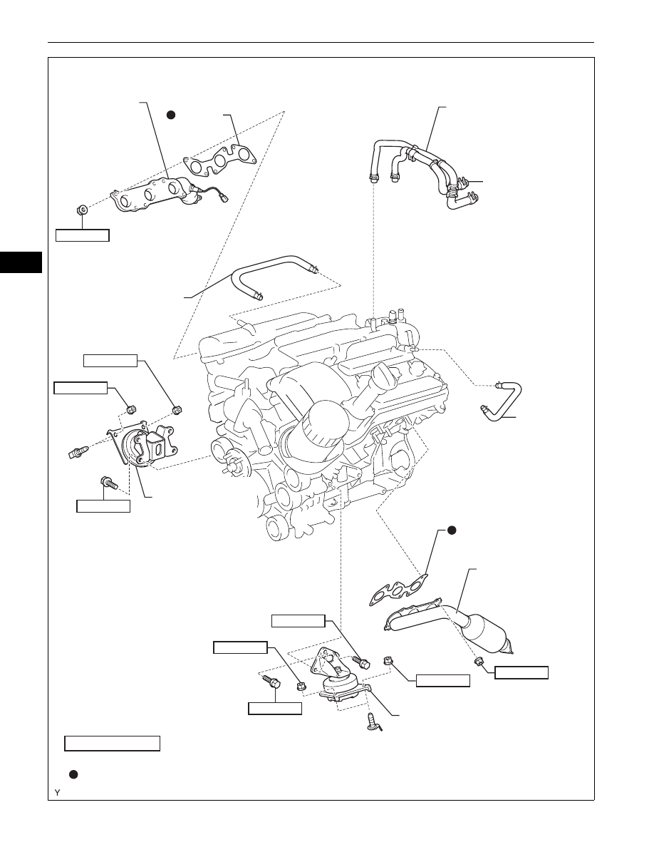
1GR-FE ENGINE MECHANICAL – ENGINE ASSEMBLY
EM
EXHAUST
MANIFOLD
SUB-ASSEMBLY
RH
NO. 2 VENTILATION
HOSE
ENGINE MOUNTING
BRACKET FRONT
NO. 1 RH
ENGINE MOUNTING BRACKET
FRONT NO. 1 LH
EXHAUST MANIFOLD
SUB-ASSEMBLY LH
VENTILATION
HOSE
HEATER WATER
OUTLET HOSE
HEATER WATER
INLET HOSE
N*m (kgf*cm, ft*lbf) : Specified torque
Non-reusable part
43 (435, 31)
GASKET
x2
38 (387, 28)
43 (435, 31)
38 (387, 28)
30 (306, 22)
x6
GASKET
30 (306, 22)
38 (387, 28)
43 (435, 31)
x4
38 (387, 28)
x6
A126455E01