Toyota FJ Cruiser (GSJ 10, 15 series). Instruction - part 142
 

  Index      Toyota     Toyota FJ Cruiser (model GSJ 10, 15 series) - service repair instruction 2007 year


Search            copyright infringement  


Content   ..  140  141  142  143   ..


Toyota FJ Cruiser (GSJ 10, 15 series). Instruction - part 142


EM–2

1GR-FE ENGINE MECHANICAL  –  ENGINE

EM

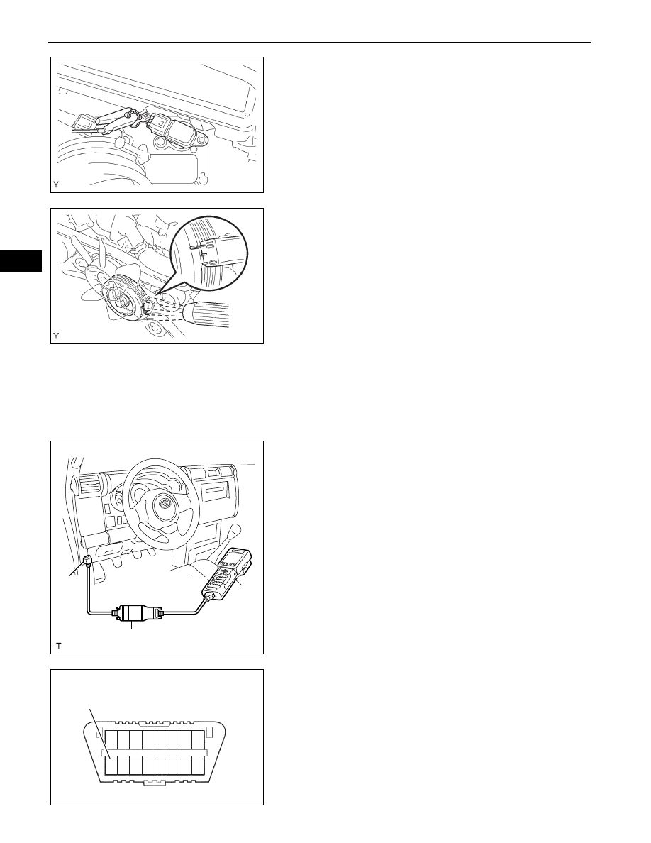
(3) Pull out the wire harness shown in the 

illustration.

(4) Connect the tester probe of a timing light to the 

wire of the ignition coil connector for the No. 1 
cylinder.
NOTICE:
•

Use timing light that detects the first 
signal.

•

After checking, wrap the wire harness 
with tape.

(5) Inspect the ignition timing during idling.

Ignition timing:

8 to 12

°CA BTDC during idling 

(Transmission in neutral position)

(6) Remove SST from the DLC3.
(7) Inspect the ignition timing during idling.

Ignition timing:

7 to 24

°CA BTDC during idling 

(Transmission in neutral position)

(8) Install the air cleaner.

8.

INSPECT ENGINE IDLING SPEED
NOTICE:
•

Turn all the electrical systems OFF.

•

Operate the inspection when the cooling fan 
motor is turned OFF.

(a) Warm up the engine.

(b) When using the intelligent tester:

(1) Connect the intelligent tester to the DLC3.
(2) Select the following menu items: DIAGNOSIS / 

ENHANCED OBD ll / DATA LIST / PRIMARY / 
ENGINE SPD.

(3) Inspect the engine idling speed.

Idling speed:

650 to 750 rpm (Transmission in neutral 
position)

(c) When not using the intelligent tester:

(1) Using SST, connect the terminal 8 (TAC) of the 

DLC3.
SST

09843-18030

(2) Race the engine speed at 2,500 rpm for 

approximately 90 seconds.

(3) Inspect the engine idling speed.

Idling speed:

650 to 750 rpm (Transmission in neutral 
position)

A076315E02

A076316E01

Intelligent Tester

DLC3

CAN VIM

A129958E01

1 2 3 4 5 6

9 1011 1213141516

7 8

TAC

DLC3

A118802E02

1GR-FE ENGINE MECHANICAL  –  ENGINE

EM–3

EM

9.

INSPECT COMPRESSION
(a) Warm up and stop the engine.
(b) Remove the circuit opening relay (See page 

ES-

443

).

(c) Remove the V-bank cover (See page 

ES-414

).

(d) Remove the air cleaner assembly (See page 

ES-

429

).

(e) Remove the throttle body bracket (See page 

FU-

11

).

(f)

Remove the oil baffle plate (See page 

FU-11

).

(g) Remove the No. 1 surge tank stay (See page 

FU-

11

).

(h) Remove the No. 2 surge tank stay (See page 

FU-

12

).

(i)

Remove the ignition coils (See page 

IG-8

).

(j)

Remove the spark plugs.

(k) Inspect the cylinder compression pressure.

(1) Insert a compression gauge into the spark plug 

hole. (*1)
SST

09992-00500

(2) Fully open the throttle. (*2)
(3) While cranking the engine, measure the 

compression pressure. (*3)
Compression pressure:

1,300 kPa (13.3 kgf/cm

2

, 189 psi)

Minimum pressure:

1,000 kPa (10.2 kgf/cm

2

, 145 psi)

Difference between cylinders:

100 kPa (1.0 kgf/cm

2

, 15 psi)

NOTICE:
•

Use a fully-charged battery so the engine 
speed can be increased to 2,500 rpm or 
more.

•

Inspect the other cylinders in the same 
way.

•

Measure the compression in as short a 
time as possible.

(4) If the cylinder compression is low, pour a small 

amount of engine oil into the cylinder through 
the spark plug hole and repeat steps (*1) 
through (*3) for cylinders with low compression.
•

If adding oil increases the compression, the 
piston rings and/or cylinder bore may be 
worn or damaged.

•

If the pressure stays low, a valve may be 
stuck or seated improperly, or there may be 
leakage from the gasket.

10. INSPECT CO/HC

(a) Start the engine.
(b) Run the engine at 2,500 rpm for approximately 180 

seconds.

(c) Insert the CO/HC meter testing probe at least 40 cm 

(1.3 ft) into the tailpipe during idling.

A076317E01

EM–4

1GR-FE ENGINE MECHANICAL  –  ENGINE

EM

(d) Immediately check the CO/HC concentration during 

idling and/or while running at 2,500 rpm.
HINT:
•

Complete the measurement within 3 minutes.

•

When carrying out the 2 mode (with the engine 
idling/running at 2,500 rpm) test, the 
measurement orders are prescribed by the 
applicable local regulations.

(e) If the CO/HC concentration does not comply with 

regulations, troubleshoot in the order given below.
(1) Check the heated oxygen sensor operation.

CO

HC

Problems

Causes

Normal

High

Rough idling

1.

Faulty ignition:
–

Incorrect timing

–

Fouled, shorted or improperly gapped plugs

2.

Incorrect valve clearance

3.

Leaking intake and exhaust valves

4.

Leaking cylinders

Low

High

Rough idling 
(Fluctuating HC reading)

1.

Vacuum leaks:
–

PCV hoses

–

Intake manifold

–

Throttle body

–

IAC  valve

–

Brake booster line

2.

Lean mixture causing misfire

High

High

Rough idling 
(Black smoke from 
exhaust)

1.

Restricted air filter

2.

Plugged PCV valve

3.

Faulty EFI systems:
–

Faulty pressure regulator

–

Faulty engine coolant temperature sensor

–

Faulty mass air flow meter

–

Faulty  ECM

–

Faulty injectors

–

Faulty throttle position sensor

1GR-FE ENGINE MECHANICAL  –  DRIVE BELT

EM–5

EM

ENGINE

1GR-FE ENGINE MECHANICAL

DRIVE BELT

COMPONENTS

FAN AND GENERATOR 
V BELT

NO. 1 ENGINE UNDER 
COVER SUB-ASSEMBLY

N*m (kgf*cm, ft*lbf)  : Specified torque

29 (296, 21)

x4

A126409E01


Content   ..  140  141  142  143   ..