Toyota FJ Cruiser (GSJ 10, 15 series). Instruction - part 141
 

  Index      Toyota     Toyota FJ Cruiser (model GSJ 10, 15 series) - service repair instruction 2007 year


Search            copyright infringement  


Content   ..  139  140  141  142   ..


Toyota FJ Cruiser (GSJ 10, 15 series). Instruction - part 141


ED–60

ENGINE HOOD / DOOR  –  BACK WINDOW SUPPORT

ED

BODY

ENGINE HOOD / DOOR

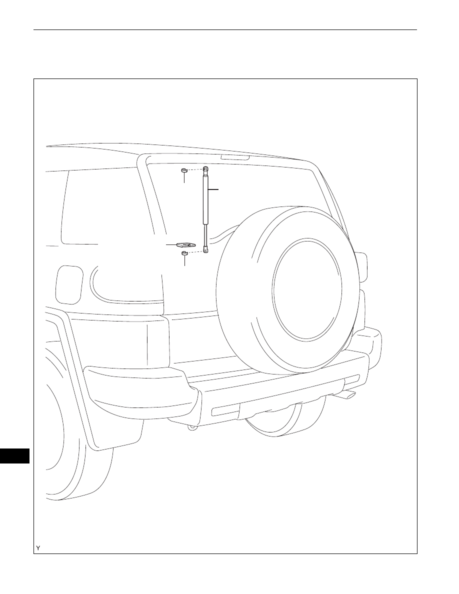
BACK WINDOW SUPPORT

COMPONENTS

BACK DOOR TRIM 
COVER

BACK WINDOW SUPPORT

CLIP

CLIP

B139384E01

ENGINE HOOD / DOOR  –  BACK WINDOW SUPPORT

ED–61

ED

REMOVAL

HINT:
•

Use the same procedure for both the RH and LH sides.

•

The procedure described below is for the LH side.

1.

REMOVE BACK DOOR TRIM COVER (See page 

ED-

48

)

2.

REMOVE BACK WINDOW SUPPORT
(a) Using a screwdriver with its tip wrapped in 

protective tape, remove the 2 stop rings and back 
window support.
NOTICE:
•

Do not touch the rod of the back window 
support with gloves, to avoid fibers from 
adhering.

•

When foreign matter adheres to the rod, it 
prevents the rod from moving smoothly and 
reduces its holding power.

HINT:
Support the back door glass by hand while 
removing the back window support.

INSTALLATION

1.

INSTALL BACK WINDOW SUPPORT
(a) Install the 2 stop rings onto the back window 

support.

(b) Install the back window support.

2.

INSTALL BACK DOOR TRIM COVER (See page 

ED-

57

)

B135523

B135551

ED–62

ENGINE HOOD / DOOR  –  BACK WINDOW SUPPORT

ED

DISPOSAL

HINT:
•

Use the same procedure for both the RH and LH sides.

•

The procedure described below is for the LH side.

1.

DISPOSE OF BACK WINDOW SUPPORT
(a) Horizontally fix the back window support in a vise 

with the piston-rod pulled out.

(b) Wearing protective glasses, using a metal saw 

gradually cut the shaded part between A and B, 
shown in the illustration, to gradually release the 
gas.
Specification

CAUTION:
•

Cover the area that is being cut with a shop 
rag or a piece of cloth because there is a 
possibility that metal shards may be 
dispersed by the gas.

•

The gas is colorless, odorless and harmless.

A

B

a

b

B135552E01

Area

Measurement

a

80 mm (3.15 in.)

b

20 mm (0.80 in.)

1GR-FE ENGINE MECHANICAL  –  ENGINE

EM–1

EM

ENGINE

ON-VEHICLE INSPECTION

1.

INSPECT ENGINE COOLANT (See page 

CO-2

)

2.

INSPECT ENGINE OIL (See page 

LU-2

)

3.

INSPECT BATTERY (See page 

CH-4

)

4.

INSPECT AIR CLEANER FILTER ELEMENT SUB-
ASSEMBLY

5.

INSPECT SPARK PLUG (See page 

IG-5

)

6.

INSPECT FAN AND GENERATOR V BELT (See page 

EM-6

)

7.

INSPECT IGNITION TIMING
NOTICE:
•

Turn all the electrical systems OFF.

•

Conduct the inspection when the cooling fan 
motor is turned OFF.

(a) Warm up the engine.

(b) When using the intelligent tester:

(1) Connect the intelligent tester to the DLC3.
(2) Select the following menu items: DIAGNOSIS / 

ENHANCED OBD ll / DATA LIST / PRIMARY / 
IGN ADVANCE.

(3) Inspect the ignition timing during idling.

Ignition timing:

7 to 24

°CA BTDC during idling 

(Transmission in neutral position) 

(4) Check that the ignition timing advances 

immediately when the engine speed is 
increased.

(c) When not using intelligent tester:

(1) Using SST, connect the terminals 13 (TC) and 

4 (CG) of the DLC3.
SST

09843-18040

NOTICE:
Do not connect the terminals incorrectly as 
it causes breakage of the engine.

(2) Remove the air cleaner.

Intelligent Tester

DLC3

CAN VIM

A129958E01

1 2 3 4 5 6

9 1011 1213141516

7 8

DLC3

TC

CG

A118802E01


Content   ..  139  140  141  142   ..