Toyota Tundra (2015 year). Manual - part 981


  Index      Toyota     Toyota Tundra (2015 year) - Service and Repair Manual


Search            copyright infringement  


Content   ..  979  980  981  982   ..


Toyota Tundra (2015 year). Manual - part 981


Last Modified: 9-16-2014

6.6 J

Doc ID: RM000003YLU03BX

Model Year: 2015

Model: Tundra

Prod Date Range: [08/2014 -           ]

Title: AUDIO / VISUAL: AUDIO AND VISUAL SYSTEM: Reverse Signal Circuit; 2015 MY Tundra [08/2014 -        ]

Reverse Signal Circuit

DESCRIPTION

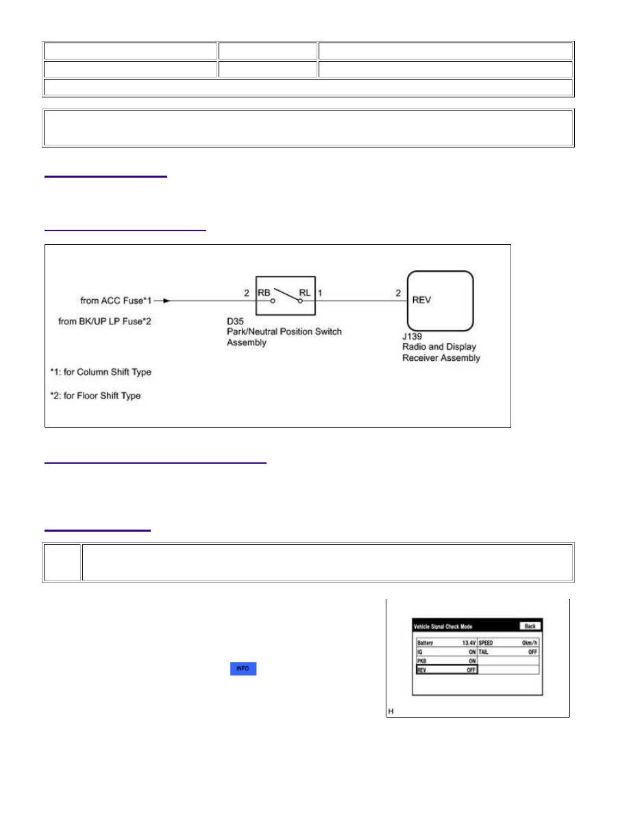
The radio and display receiver assembly receives a reverse signal from the park/neutral position switch assembly.

WIRING DIAGRAM

INSPECTION PROCEDURE

NOTICE:

Inspect the fuses for circuits related to this system before performing the following inspection procedure.

PROCEDURE

1.

CHECK VEHICLE SIGNAL (OPERATION CHECK)

(a) Enter the "Vehicle Signal Check Mode" screen. [Refer to check

Vehicle Signal in Operation Check 


].

(b) Check that the display changes between ON and OFF according to the shift lever position.

OK:

AUDIO / VISUAL: AUDIO AND VISUAL SYSTEM: Reverse Signal C...

SHIFT LEVER POSITION

DISPLAY

R

ON

Except R

OFF

HINT:

This display is updated once per second. As a result, it is normal for the display to lag behind the actual

shift lever position.

NG

GO TO STEP 2

OK

PROCEED TO NEXT SUSPECTED AREA SHOWN IN

PROBLEM SYMPTOMS TABLE

2.

CHECK RADIO AND DISPLAY RECEIVER ASSEMBLY

(a) Disconnect the radio and display receiver assembly connector.

(b) Measure the voltage according to the value(s) in the table

below.

Standard Voltage:

TESTER CONNECTION

SWITCH CONDITION

SPECIFIED

CONDITION

J139-2 (REV) - Body

ground

Ignition switch ON, shift

lever in R

7.5 to 14 V

J139-2 (REV) - Body

ground

Ignition switch ON, shift

lever not in R

Below 1 V

Text in Illustration

*a

Result

RESULT

PROCEED TO

OK (for Column Shift Type)

A

OK (for Floor Shift Type)

B

NG

C

B

REPLACE RADIO AND DISPLAY RECEIVER ASSEMBLY

C

GO TO STEP 3

AUDIO / VISUAL: AUDIO AND VISUAL SYSTEM: Reverse Signal C...

OK

A

REPLACE RADIO AND DISPLAY RECEIVER ASSEMBLY

3.

CHECK HARNESS AND CONNECTOR (RADIO AND DISPLAY RECEIVER ASSEMBLY -
PARK/NEUTRAL POSITION SWITCH ASSEMBLY)

(a) Disconnect the J139 radio and display receiver assembly connector.

(b) Disconnect the D35 park/neutral position switch assembly connector.

(c) Measure the resistance according to the value(s) in the table below.

Standard Resistance:

TESTER CONNECTION

CONDITION

SPECIFIED CONDITION

J139-2 (REV) - D35-1 (RL)

Always

Below 1 Ω

J139-2 (REV) - Body ground

Always

10 kΩ or higher

NG

REPAIR OR REPLACE HARNESS OR CONNECTOR

4.

CHECK HARNESS AND CONNECTOR (PARK/NEUTRAL POSITION SWITCH ASSEMBLY -
BATTERY)

(a) Disconnect the park/neutral position switch assembly

connector.

(b) Measure the voltage according to the value(s) in the table below.

Standard Voltage:

TESTER CONNECTION

SWITCH CONDITION

SPECIFIED CONDITION

D35-2 (RB) - Body ground

Ignition switch ON

11 to 14 V

Text in Illustration

*a

(to Park/neutral Position Switch Assembly)

HINT:

If replacing the park/neutral position switch assembly, refer to the procedures below.

for A760E: 
for A760F: 
for AB60E: 

for AB60F: 

NG

REPAIR OR REPLACE HARNESS OR CONNECTOR

OK

REPLACE PARK/NEUTRAL POSITION SWITCH

ASSEMBLY

AUDIO / VISUAL: AUDIO AND VISUAL SYSTEM: Reverse Signal C...


Content   ..  979  980  981  982   ..