Toyota Tundra (2015 year). Manual - part 982
Last Modified: 9-16-2014
6.6 J
Doc ID: RM000005KRN009X
Model Year: 2015
Model: Tundra
Prod Date Range: [08/2014 - ]
Title: AUDIO / VISUAL: AUDIO AND VISUAL SYSTEM: Display Signal Circuit between Radio Receiver and
Extension Module; 2015 MY Tundra [08/2014 - ]
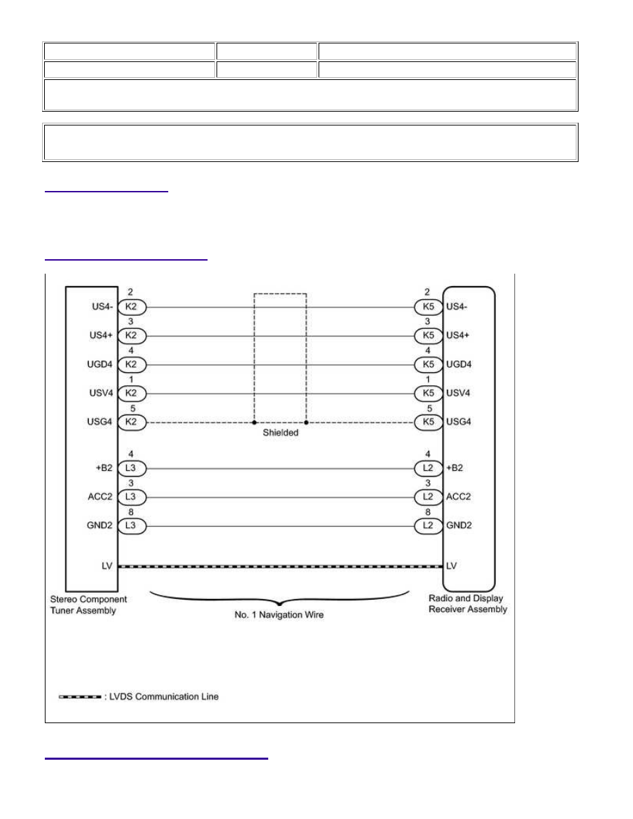
Display Signal Circuit between Radio Receiver and Extension Module
DESCRIPTION
The stereo component tuner assembly sends the sound data signal or image data signal from a device to the
radio and display receiver assembly via this circuit.
WIRING DIAGRAM
INSPECTION PROCEDURE
AUDIO / VISUAL: AUDIO AND VISUAL SYSTEM: Display Signal C...