Toyota Tundra (2015 year). Manual - part 979
OK
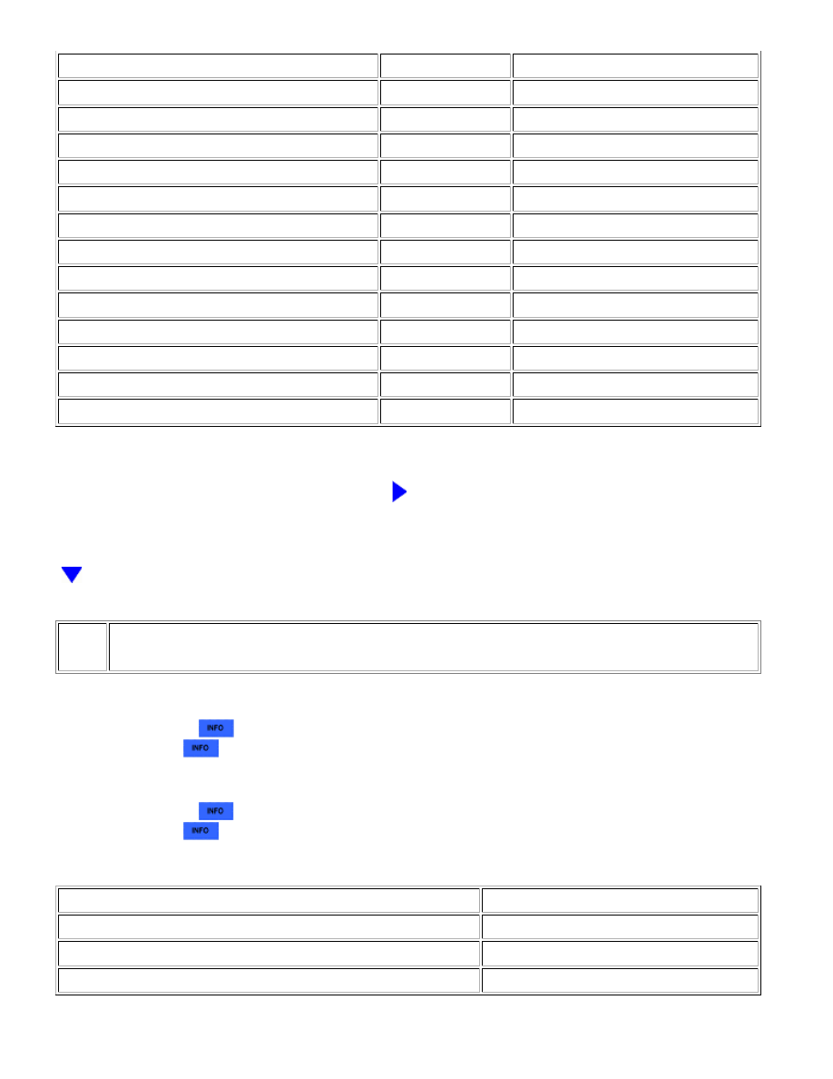
TESTER CONNECTION
CONDITION
SPECIFIED CONDITION
J138-6 (RL-) - O8-2*
Always
Below 1 Ω
J145-5 (WFL+) - O7-1
Always
Below 1 Ω
J145-12 (WFL-) - O7-2
Always
Below 1 Ω
J137-2 (FL+) - Body ground
Always
10 kΩ or higher
J137-6 (FL-) - Body ground
Always
10 kΩ or higher
J149-1 (+) - Body ground
Always
10 kΩ or higher
J149-4 (-) - Body ground
Always
10 kΩ or higher
J144-2 (L+) - Body ground
Always
10 kΩ or higher
J144-6 (L-) - Body ground
Always
10 kΩ or higher
J138-2 (RL+) - Body ground
Always
10 kΩ or higher
J138-6 (RL-) - Body ground
Always
10 kΩ or higher
J145-5 (WFL+) - Body ground
Always
10 kΩ or higher
J145-12 (WFL-) - Body ground
Always
10 kΩ or higher
*: for 9 Speakers
NG
REPAIR OR REPLACE HARNESS OR CONNECTOR
10.
INSPECT FRONT NO. 1 SPEAKER ASSEMBLY
(a) Remove the front No. 1 speaker assembly.
for Double Cab:
for CrewMax:
(b) Inspect the front No. 1 speaker assembly.
for Double Cab:
for CrewMax:
Result
RESULT
PROCEED TO
OK
A
NG (for Double Cab)
B
NG (for CrewMax)
C
AUDIO / VISUAL: AUDIO AND VISUAL SYSTEM: Speaker Circuit;...