Toyota Tundra (2015 year). Manual - part 820


  Index      Toyota     Toyota Tundra (2015 year) - Service and Repair Manual


Search            copyright infringement  


Content   ..  818  819  820  821   ..


Toyota Tundra (2015 year). Manual - part 820


Last Modified: 9-16-2014

6.6 A

Doc ID: RM0000016WV02PX

Model Year: 2015

Model: Tundra

Prod Date Range: [08/2014 -           ]

Title: DRIVE SHAFT: FRONT DRIVE SHAFT ASSEMBLY (for 4WD): REMOVAL; 2015 MY Tundra [08/2014 -        ]

REMOVAL

HINT:

Use the same procedures for the RH side and LH side.
The procedures listed below are for the LH side.

1. REMOVE FRONT WHEEL

2. REMOVE NO. 1 ENGINE UNDER COVER 

3. DRAIN DIFFERENTIAL OIL 

4. DISCONNECT FRONT SPEED SENSOR LH

(a) Disconnect the front speed sensor LH 


.

5. REMOVE FRONT AXLE HUB GREASE CAP 

6. REMOVE AXLE HUB NUT 

7. REMOVE TIE ROD END SUB-ASSEMBLY 

8. DISCONNECT FRONT LOWER BALL JOINT ATTACHMENT LH 

9. DISCONNECT FRONT DRIVE SHAFT ASSEMBLY LH

(a) Using plastic-faced hammer, disconnect the drive shaft from the axle hub side.

(b) Push the steering knuckle outward and disconnect the drive shaft from the steering knuckle.

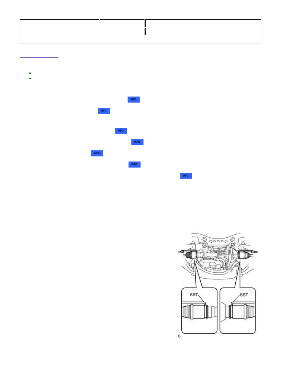
10. REMOVE FRONT DRIVE SHAFT ASSEMBLY LH

(a) Using SST, remove the drive shaft.

SST: 09520-01010

SST: 09520-24010

09520-32040

NOTICE:

Be careful not to damage the dust cover and oil seal.

DRIVE SHAFT: FRONT DRIVE SHAFT ASSEMBLY (for 4WD): R...

(b) Using a screwdriver, remove the snap ring from the inboard joint shaft.

DRIVE SHAFT: FRONT DRIVE SHAFT ASSEMBLY (for 4WD): R...

Last Modified: 9-16-2014

6.6 A

Doc ID: RM0000016WW02VX

Model Year: 2015

Model: Tundra

Prod Date Range: [08/2014 -           ]

Title: DRIVE SHAFT: FRONT DRIVE SHAFT ASSEMBLY (for 4WD): DISASSEMBLY; 2015 MY Tundra [08/2014 -

       ]

DISASSEMBLY

1. REMOVE INBOARD JOINT BOOT CLAMP

(a) Using a side cutter, cut the 2 inboard joint boot clamps and remove them.

2. DISCONNECT INBOARD JOINT BOOT

(a) Disconnect the inboard joint boot from the inboard joint shaft.

3. REMOVE INBOARD JOINT SHAFT

(a) Place matchmarks on the inboard joint shaft and outboard joint

shaft.

NOTICE:

Do not punch the marks.

(b) Using a screwdriver, remove the snap ring from the outboard joint shaft.

(c) Remove the inboard joint shaft from the outboard joint shaft.

(d) Place matchmarks on the outboard joint shaft, inner race and

cage.

NOTICE:

Do not punch the marks.

(e) Remove the 6 balls.

(f) Slide the cage to the outboard joint side.

(g) Using a snap ring expander, remove the snap ring.

DRIVE SHAFT: FRONT DRIVE SHAFT ASSEMBLY (for 4WD): DI...

(h) Using a brass bar and hammer, tap out the inner race.

NOTICE:

Be careful not to damage the inner race.

(i) Remove the cage.

4. REMOVE INBOARD JOINT BOOT

(a) Remove the inboard joint boot from the outboard joint shaft.

5. REMOVE OUTBOARD JOINT BOOT CLAMP

(a) Using a side cutter, cut the 2 outboard joint boot clamps and remove them.

6. REMOVE OUTBOARD JOINT BOOT

(a) Remove the outboard joint boot from the outboard joint shaft.

7. REMOVE FRONT DRIVE SHAFT DUST COVER LH

(a) Using SST and a press, press out the dust cover.

SST: 09950-00020

8. REMOVE DUST SEAL

(a) Using SST and a press, press out the dust seal.

SST: 09950-00020

DRIVE SHAFT: FRONT DRIVE SHAFT ASSEMBLY (for 4WD): DI...


Content   ..  818  819  820  821   ..