Toyota Tundra (2015 year). Manual - part 815


  Index      Toyota     Toyota Tundra (2015 year) - Service and Repair Manual


Search            copyright infringement  


Content   ..  813  814  815  816   ..


Toyota Tundra (2015 year). Manual - part 815


THICKNESS

THICKNESS

1.940 to 1.960 mm (0.0764 to 0.0771 in.)

2.190 to 2.210 mm (0.0863 to 0.0870 in.)

1.965 to 1.985 mm (0.0774 to 0.0781 in.)

2.215 to 2.235 mm (0.0872 to 0.0879 in.)

1.990 to 2.010 mm (0.0784 to 0.0791 in.)

2.240 to 2.260 mm (0.0882 to 0.0889 in.)

2.015 to 2.035 mm (0.0794 to 0.0801 in.)

2.265 to 2.285 mm (0.0892 to 0.0899 in.)

2.040 to 2.060 mm (0.0803 to 0.0811 in.)

-

25. REMOVE FRONT DRIVE PINION COMPANION FLANGE FRONT NUT 

26. REMOVE FRONT DRIVE PINION FRONT COMPANION FLANGE SUB-ASSEMBLY 

27. REMOVE FRONT DIFFERENTIAL DRIVE PINION OIL SLINGER

28. REMOVE FRONT DIFFERENTIAL CROSS SHAFT BEARING RETAINER 

29. REMOVE FRONT DIFFERENTIAL CASE 

30. REMOVE DIFFERENTIAL DRIVE PINION 

31. REMOVE FRONT DRIVE PINION FRONT RADIAL BALL BEARING

32. INSTALL FRONT DIFFERENTIAL DRIVE PINION BEARING SPACER

(a) Install a new bearing spacer.

33. TEMPORARILY INSTALL DIFFERENTIAL DRIVE PINION

34. INSTALL FRONT DIFFERENTIAL CASE

35. INSTALL FRONT DIFFERENTIAL CROSS SHAFT BEARING RETAINER

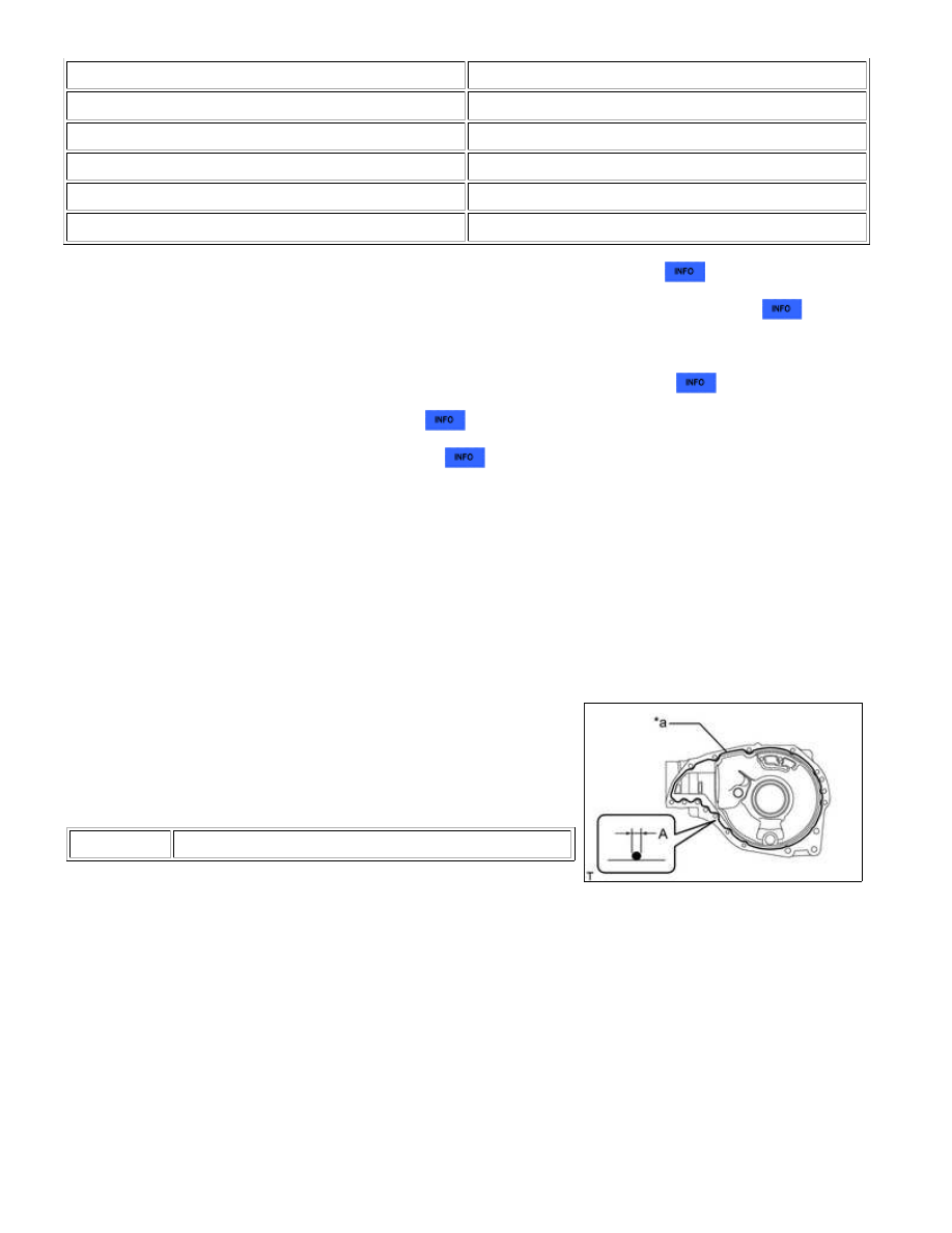
(a) Remove any old FIPG material and be careful not to drop oil on

Text in Illustration

*a

Seal Packing

(b) Clean the contact surfaces with any residual FIPG material using gasoline or alcohol.

(c) Apply seal packing to the differential carrier as shown in the illustration.

Seal packing:

Toyota Genuine Seal Packing 1281, Three Bond 1281 or equivalent

Standard Seal Diameter (A):

2.0 to 3.0 mm (0.0788 to 0.118 in.)

HINT:

(d) Install the front differential cross shaft bearing retainer and

front differential front support assembly LH with the 11 bolts (A),

and 3 bolts (B).

Torque:

for bolt A -

65 N·m {633 kgf·cm, 48ft·lbf}

for bolt B -

155 N·m {1581 kgf·cm, 114ft·lbf}

NOTICE:

Do not add oil or drive the vehicle immediately after installing

the cover, and leave it as is for at least an hour. Also, for 12
hours or less, avoid rapid acceleration/deceleration.

36. INSTALL FRONT DRIVE PINION FRONT RADIAL BALL BEARING

(a) Using SST and a hammer, lightly tap in the bearing (inner race)

to install it.

SST: 09316-60011

09316-00041

37. INSTALL FRONT DIFFERENTIAL DRIVE PINION OIL SLINGER

38. INSTALL FRONT DIFFERENTIAL CARRIER OIL SEAL

(a) Using SST and a hammer, tap in a new oil seal.

SST: 09502-12010

SST: 09316-60011

09316-00041

Standard oil seal depth:

5.6 to 6.6 mm (0.221 to 0.259 in.)

DIFFERENTIAL: FRONT DIFFERENTIAL CARRIER ASSEMBLY (f...

(a) Using SST, install the companion flange.

SST: 09950-30012

09951-03010

09953-03010

09954-03010

09955-03030

09956-03020

Text in Illustration

*a

Turn

*b

Hold

(b) Using SST to hold the companion flange.

SST: 09330-00021

09330-00030

Torque:

451 N·m {4599 kgf·cm, 333ft·lbf} or less

Standard total preload (at starting):

BEARING

SPECIFIED CONDITION

New

2.97 to 3.47 N*m (31 to 35 kgf*cm, 27 to 30 in.*lbf)

Reused

2.14 to 2.45 N*m (22 to 24 kgf*cm, 19 to 21 in.*lbf)

If the preload is more than the specification, replace the

bearing spacer.

If the preload is less than the specification, tighten the nut with

Torque:

451 N·m {4599 kgf·cm, 333ft·lbf}or less

If the maximum torque is exceeded while tightening the nut,

replace the bearing spacer and repeat the preload procedure.

HINT:

DIFFERENTIAL: FRONT DIFFERENTIAL CARRIER ASSEMBLY (f...

Do not loosen the nut to reduce the preload.

40. INSPECT TOTAL PRELOAD

Standard total preload (at starting):

BEARING

SPECIFIED CONDITION

New

Drive pinion preload + 1.61 to 2.41 N*m (17 to 24

kgf*cm, 15 to 21 in.*lbf)

Reused

Drive pinion preload + 1.33 to 2.13 N*m (14 to 21

kgf*cm, 12 to 18 in.*lbf)

41. INSPECT BACKLASH BETWEEN DIFFERENTIAL RING GEAR AND DIFFERENTIAL DRIVE

PINION

(a) Using SST and a dial indicator, measure the ring gear backlash.

SST: 09564-33010

Standard backlash:

0.17 to 0.27 mm (0.00670 to 0.0106 in.)

42. INSPECT RUNOUT OF FRONT DRIVE PINION COMPANION FLANGE SUB-ASSEMBLY

Text in Illustration

*a

55 mm (2.17 in.)

Maximum runout:

RUNOUT

SPECIFIED CONDITION

Vertical runout

0.10 mm (0.00394 in.)

Lateral runout

0.10 mm (0.00394 in.)

If the runout is more than the maximum, replace the companion

flange.

43. STAKE FRONT DRIVE PINION COMPANION FLANGE FRONT NUT

DIFFERENTIAL: FRONT DIFFERENTIAL CARRIER ASSEMBLY (f...


Content   ..  813  814  815  816   ..